Tact Switch

A switch used to control circuits and other electronic components.
It can be connected to a digital pin on Arduino and used as an input signal.
A button cap can be attached for use.
How to Use
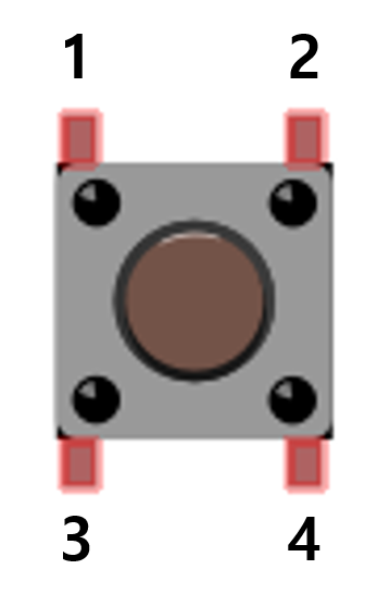
- [1, 3] and [2, 4] are connected together, and pressing the button connects all numbers.
Connection and Example of Use
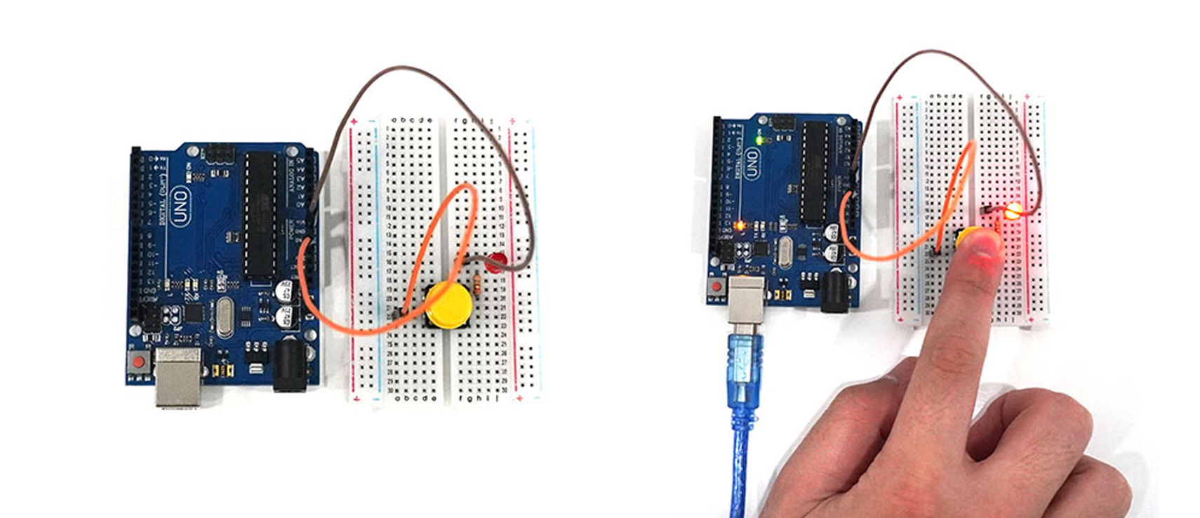
- When the switch is pressed, an LED lights up. No separate coding is provided.
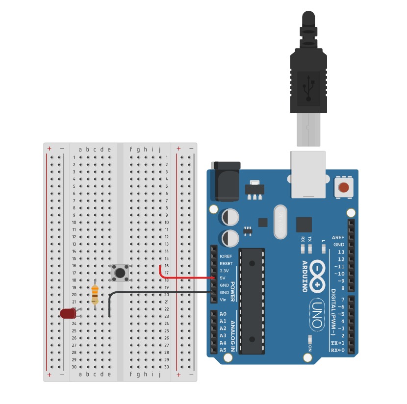
Execution Result
Floating Phenomenon and Pull-up, Pull-down Resistors
Floating Phenomenon
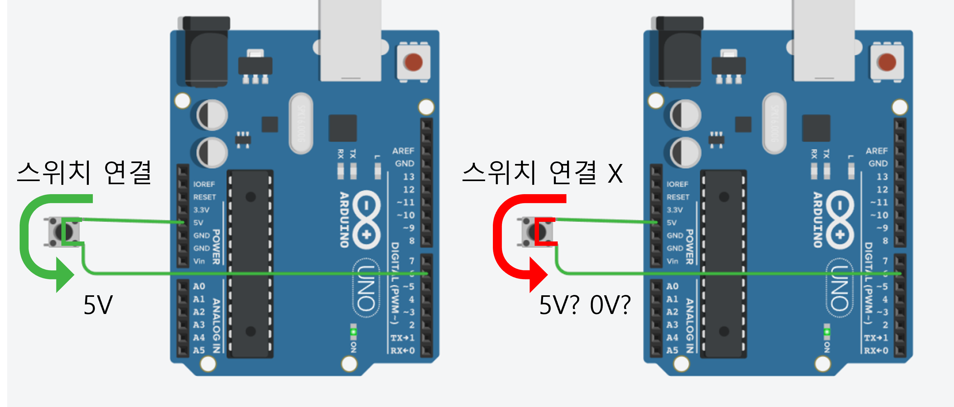
The floating phenomenon refers to the state where the input pin of a switch or button is not properly connected to any voltage.
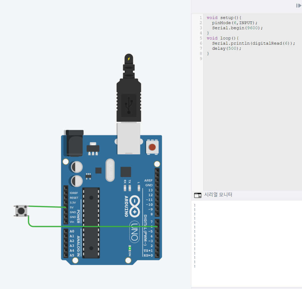
In the circuit above, when the switch is connected, a 5V (HIGH) signal is connected to pin 6.
However, when the switch is not connected, it's unclear whether pin 6 is HIGH or LOW.
Even without pressing the switch, the serial monitor may show the output of pin 6 as 1 (HIGH).
To solve this floating phenomenon, pull-up or pull-down resistors are needed.
Pull-up Resistor
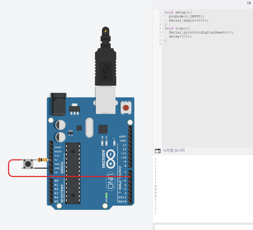
A resistor is added between the input pin and 5V.
When the switch is open, it remains 1 (HIGH), and when the switch is closed, it is shorted to GND, maintaining 0 (LOW).
Pull-down Resistor
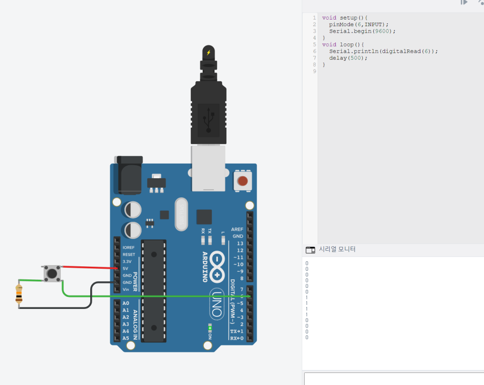
A resistor is added between the input pin and GND.
When the switch is open, it is shorted to GND, maintaining 0 (LOW), and when the switch is closed, it remains 1 (HIGH).
Arduino Internal Pull-up Resistor (INPUT_PULLUP)
Arduino has a built-in pull-up resistor.
When setting the digital input pin mode, using 'INPUT_PULLUP' allows you to use the digital pin as a pull-up resistor without adding an external resistor.
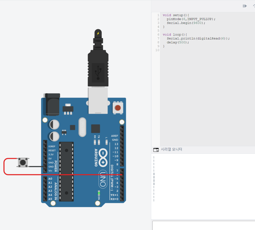
Setting pinMode to INPUT_PULLUP without adding a separate resistor yields the same result as using a pull-up resistor.