NeoPixel(WS2812): 두 판 사이의 차이
잔글편집 요약 없음 |
잔글편집 요약 없음 |
||
| 1번째 줄: | 1번째 줄: | ||
[[File:네오픽셀대표이미지1.jpg|center|class=coders100]] | [[File:네오픽셀대표이미지1.jpg|center|class=coders100]] | ||
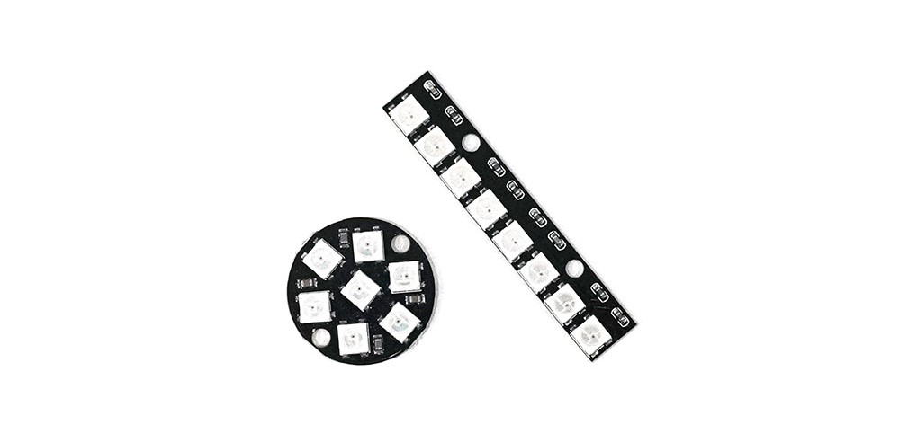
A single LED that can display multiple colors by adjusting RGB values, with each LED individually controllable by a controller. | |||
In the text, two models were used: a circular one with 7 LEDs and a linear one with 8 LEDs. | |||
The terminals total either 6 or 8, with the 6-terminal version comprising (IN, 2x VCC, 2x GND, OUT), and the 8-terminal version adding 2 more GNDs to the 6-terminal setup. | |||
Connecting the OUT terminal of a NeoPixel to the IN terminal of the next allows for controlling multiple NeoPixels with just one pin on the board. | |||
== '''Specifications''' == | |||
* Operating Voltage: 5V | |||
* Current per LED: 20mA ~ 80mA | |||
== '''Required Hardware''' == | |||
== ''' | |||
* NeoPixel | * NeoPixel | ||
| 24번째 줄: | 22번째 줄: | ||
* F-M cable(3ea) | * F-M cable(3ea) | ||
== ''' | == '''Connection (M-M and F-M cables were soldered for connection to the NeoPixel)''' == | ||
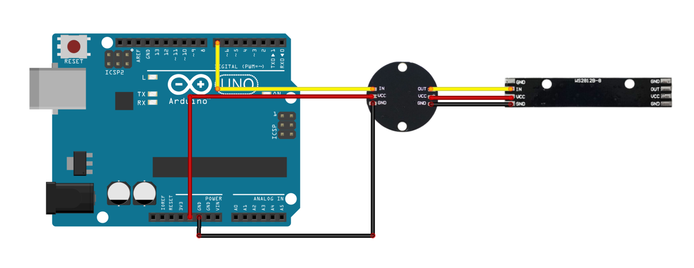
* NeoPixel to Arduino Connection | |||
{| class="wikitable" | {| class="wikitable" | ||
| | |+ | ||
!NeoPixel | |||
!Arduino | |||
|- | |- | ||
|IN | |||
|D7 | |||
|- | |- | ||
|VCC | |||
|5V | |||
|- | |- | ||
|GND | |||
|GND | |||
|} | |} | ||
* Connection between the 1st and 2nd NeoPixel (apply the same method to add more NeoPixels): | |||
* | |||
{| class="wikitable" | {| class="wikitable" | ||
| | |+ | ||
!1st NeoPixel | |||
!2nd NeoPixel | |||
|- | |- | ||
|OUT | |||
|IN | |||
|- | |- | ||
|VCC | |||
|VCC | |||
|- | |- | ||
|GND | |||
|GND | |||
|} | |} | ||
[[ | [[File:WS2812 회로.png|center|class=coders100]] | ||
== ''' | == '''Library''' == | ||
* Adafruit NeoPixel | * Adafruit NeoPixel ([[Arduino Libraries]]) | ||
[[ | |||
== '''예제 코드''' == | == '''예제 코드''' == | ||
| 69번째 줄: | 64번째 줄: | ||
#include <Adafruit_NeoPixel.h> | #include <Adafruit_NeoPixel.h> | ||
// | // Using pin number 7 | ||
#define PIN 7 | #define PIN 7 | ||
// | // Number of pixels | ||
#define NUMPIXELS 15 | #define NUMPIXELS 15 | ||
// | // Brightness level | ||
#define bright 255 | #define bright 255 | ||
#define dly 10000 | #define dly 10000 | ||
// | // Create a NeoPixel object for control | ||
Adafruit_NeoPixel neo(NUMPIXELS, PIN, NEO_GRB + NEO_KHZ800); | Adafruit_NeoPixel neo(NUMPIXELS, PIN, NEO_GRB + NEO_KHZ800); | ||
void setup() { | void setup() { | ||
// | // Start NeoPixel | ||
neo.begin(); | neo.begin(); | ||
// | // Set NeoPixel brightness | ||
neo.setBrightness(bright); | neo.setBrightness(bright); | ||
// | // Initialize NeoPixel | ||
neo.clear(); | neo.clear(); | ||
// | // Apply NeoPixel settings | ||
//.show() | // Settings are applied internally until .show() is executed. | ||
//.show() | // When .show() runs, the commands applied internally are executed on the LEDs. | ||
neo.show(); | neo.show(); | ||
} | } | ||
| 94번째 줄: | 89번째 줄: | ||
void loop() | void loop() | ||
{ | { | ||
// | // Turn LEDs white | ||
for (int i = 0; i < 15; i++) | for (int i = 0; i < 15; i++) | ||
{ | { | ||
neo.setPixelColor(i,255,255,255); | neo.setPixelColor(i, 255, 255, 255); | ||
} | } | ||
neo.show(); | neo.show(); | ||
delay(500); | delay(500); | ||
// | // Turn LEDs red | ||
for (int i = 0; i < 15; i++) | for (int i = 0; i < 15; i++) | ||
{ | { | ||
neo.setPixelColor(i,255,0,0); | neo.setPixelColor(i, 255, 0, 0); | ||
} | } | ||
neo.show(); | neo.show(); | ||
delay(500); | delay(500); | ||
// | // Turn LEDs green | ||
for (int i = 0; i < 15; i++) | for (int i = 0; i < 15; i++) | ||
{ | { | ||
neo.setPixelColor(i,0,255,0); | neo.setPixelColor(i, 0, 255, 0); | ||
} | } | ||
neo.show(); | neo.show(); | ||
delay(500); | delay(500); | ||
// | // Turn LEDs blue | ||
for (int i = 0; i < 15; i++) | for (int i = 0; i < 15; i++) | ||
{ | { | ||
neo.setPixelColor(i,0,0,255); | neo.setPixelColor(i, 0, 0, 255); | ||
} | } | ||
neo.show(); | neo.show(); | ||
delay(500); | delay(500); | ||
} | } | ||
</syntaxhighlight> | </syntaxhighlight> | ||
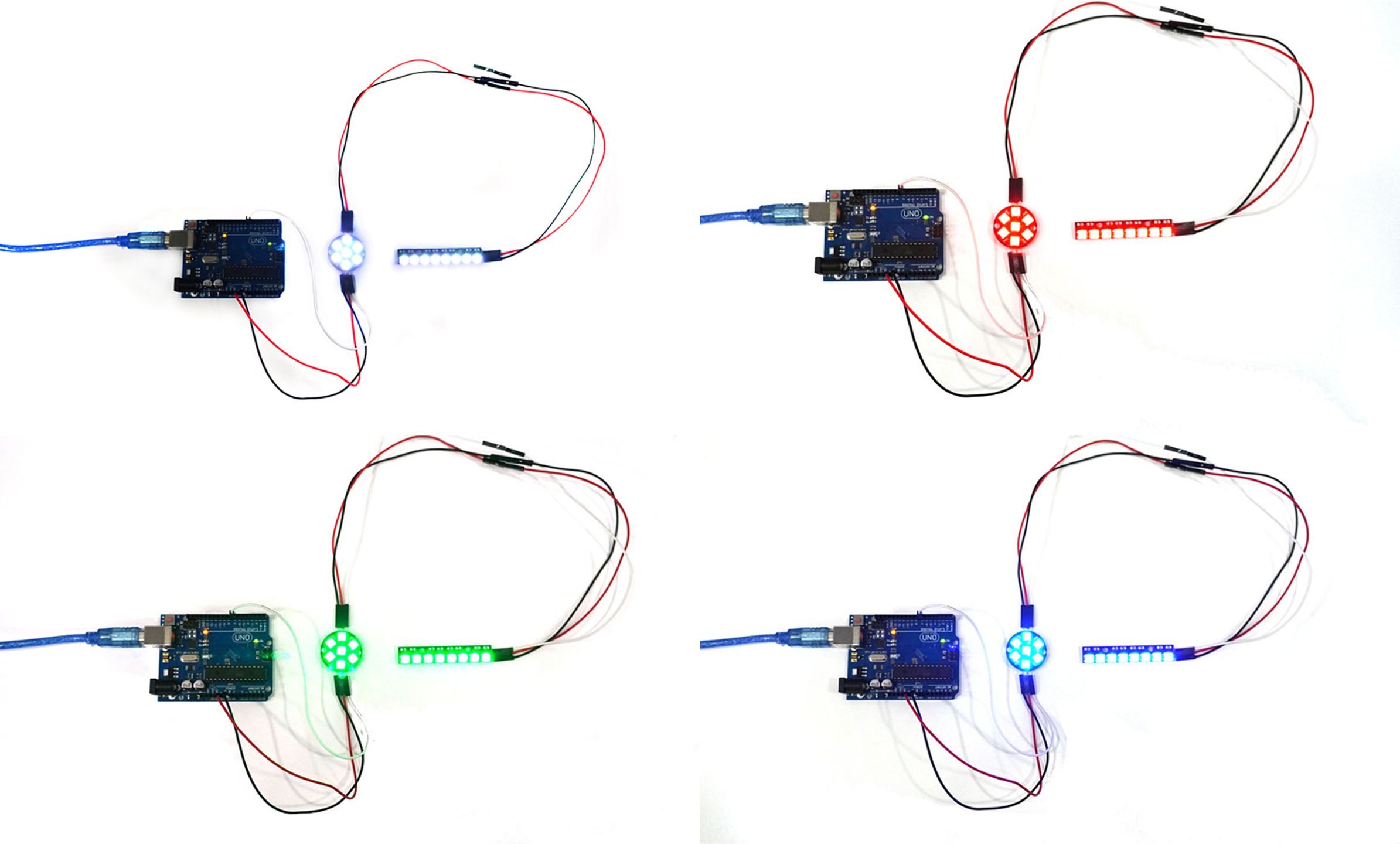
=== | === Execution Result === | ||
[[ | [[File:Ws2812 시연.png|center|class=coders100]] | ||
2024년 3월 23일 (토) 16:43 판

A single LED that can display multiple colors by adjusting RGB values, with each LED individually controllable by a controller.
In the text, two models were used: a circular one with 7 LEDs and a linear one with 8 LEDs.
The terminals total either 6 or 8, with the 6-terminal version comprising (IN, 2x VCC, 2x GND, OUT), and the 8-terminal version adding 2 more GNDs to the 6-terminal setup.
Connecting the OUT terminal of a NeoPixel to the IN terminal of the next allows for controlling multiple NeoPixels with just one pin on the board.
Specifications
- Operating Voltage: 5V
- Current per LED: 20mA ~ 80mA
Required Hardware
- NeoPixel
- Arduino UNO
- UNO cable
- M-M cable(6ea)
- F-M cable(3ea)
Connection (M-M and F-M cables were soldered for connection to the NeoPixel)
- NeoPixel to Arduino Connection
| NeoPixel | Arduino |
|---|---|
| IN | D7 |
| VCC | 5V |
| GND | GND |
- Connection between the 1st and 2nd NeoPixel (apply the same method to add more NeoPixels):
| 1st NeoPixel | 2nd NeoPixel |
|---|---|
| OUT | IN |
| VCC | VCC |
| GND | GND |

Library
- Adafruit NeoPixel (Arduino Libraries)
예제 코드
#include <Adafruit_NeoPixel.h>

// Using pin number 7
#define PIN        7
// Number of pixels
#define NUMPIXELS 15
// Brightness level
#define bright 255
#define dly 10000
// Create a NeoPixel object for control
Adafruit_NeoPixel neo(NUMPIXELS, PIN, NEO_GRB + NEO_KHZ800);

void setup() {
    // Start NeoPixel
    neo.begin();
    // Set NeoPixel brightness
    neo.setBrightness(bright);
    // Initialize NeoPixel
    neo.clear();
    // Apply NeoPixel settings
    // Settings are applied internally until .show() is executed.
    // When .show() runs, the commands applied internally are executed on the LEDs.
    neo.show();
}

void loop()
{
    // Turn LEDs white
    for (int i = 0; i < 15; i++)
    {
        neo.setPixelColor(i, 255, 255, 255);
    }
    neo.show();
    delay(500);

    // Turn LEDs red
    for (int i = 0; i < 15; i++)
    {
        neo.setPixelColor(i, 255, 0, 0);
    }
    neo.show();
    delay(500);

    // Turn LEDs green
    for (int i = 0; i < 15; i++)
    {
        neo.setPixelColor(i, 0, 255, 0);
    }
    neo.show();
    delay(500);

    // Turn LEDs blue
    for (int i = 0; i < 15; i++)
    {
        neo.setPixelColor(i, 0, 0, 255);
    }
    neo.show();
    delay(500);
}
Execution Result
