Vibration Sensor(SW-420): 두 판 사이의 차이
(새 문서: {{#seo:|title=Arduwiki : Arduino Vibration Sensor(SW-420) Guide|title_mode=append|keywords=Arduino, Information Science, Maker Learning, Performance Assessment, Vibration Sensor(SW-420), Arduino Project, Capstone Project, Arduino Example Code|description=This introduces how to control a Vibration Sensor(SW-420) with Arduino (basic information, circuit, example code). It can be used in Information Science and Maker classes.}} 파일:아두이노진동감지센서SW-420대표...) |
잔글편집 요약 없음 |
||
| 3번째 줄: | 3번째 줄: | ||
[[파일:아두이노진동감지센서SW-420대표이미지1.jpg|가운데|class=coders100]] | [[파일:아두이노진동감지센서SW-420대표이미지1.jpg|가운데|class=coders100]] | ||
== ''' | == '''Overview''' == | ||
SW-420 | The SW-420 sensor is a vibration detection sensor primarily used for detecting vibrations or shocks. This sensor can be used with microcontrollers such as Arduino for various projects. | ||
==== | ==== 1. Vibration Detection Structure ==== | ||
It uses a mechanical switch that contains a metal ball inside. The metal ball is positioned between two electrodes within the sensor, and when external vibrations or shocks occur, the ball moves to make or break contact between the electrodes. | |||
==== | ==== 2. Operating Principle ==== | ||
'''Normal State''': When the sensor is in a stable state, the metal ball does not make contact between the electrodes, resulting in a LOW (0V) output signal. | |||
'''Vibration Detection''': When vibrations occur externally, the metal ball moves and makes contact with the electrodes. At this point, the output signal changes to HIGH (5V). This signal is transmitted to a microcontroller like Arduino, indicating that a vibration has been detected. | |||
==== 3. Sensitivity Adjustment ==== | |||
The SW-420 sensor has a built-in variable resistor that allows for sensitivity adjustment. By adjusting this resistor, the strength of the vibrations detected by the sensor can be controlled. In other words, increasing the sensitivity allows for the detection of weaker vibrations, while decreasing it makes the sensor only respond to stronger vibrations. | |||
== '''Specifications''' == | |||
* ''' | *'''Voltage Range''': DC 3.3V ~ 5V | ||
* ''' | *'''Signal Type''': Digital Output (HIGH/LOW) | ||
* '''PCB | *'''Output Voltage''': Approximately 5V in HIGH state, 0V in LOW state | ||
*'''PCB Size''': Approximately 32mm x 14mm | |||
== ''' | == '''Application Examples''' == | ||
=== | === Basic Circuit Configuration === | ||
{| class="wikitable" | {| class="wikitable" | ||
! | !Arduino | ||
!SW-420 | !SW-420 Vibration Sensor | ||
|- | |- | ||
|'''5V''' | |'''5V''' | ||
|VCC | |VCC | ||
|- | |- | ||
|'''GND''' | |'''GND''' | ||
|GND | |GND | ||
|- | |- | ||
|'''D2''' | |'''D2''' | ||
|DO | |DO | ||
|} | |} | ||
[[파일:Sw420기본회로.jpg|가운데|class=coders100]] | [[파일:Sw420기본회로.jpg|가운데|class=coders100]] | ||
=== 1. | |||
=== 1. Detecting Vibration and Outputting to Serial Monitor === | |||
const int sensorPin = 2; // SW-420 OUT | After constructing the basic circuit above, this is an example of checking whether the SW-420 vibration sensor detects vibrations by shaking it with your hand and observing the output on the serial monitor. | ||
<syntaxhighlight lang="c++" line="1"> | |||
const int sensorPin = 2; // SW-420 OUT Pin Connect | |||
int sensorValue = 0; | int sensorValue = 0; | ||
| 58번째 줄: | 60번째 줄: | ||
sensorValue = digitalRead(sensorPin); | sensorValue = digitalRead(sensorPin); | ||
if (sensorValue == HIGH) { | if (sensorValue == HIGH) { | ||
Serial.println(" | Serial.println("Vibration Detection!"); | ||
} else { | } else { | ||
Serial.println(" | Serial.println("No Vibration."); | ||
} | } | ||
delay(500); | delay(500); | ||
| 66번째 줄: | 68번째 줄: | ||
</syntaxhighlight> | </syntaxhighlight> | ||
==== | ==== Execution Result ==== | ||
[[파일:Sw420예제1시리얼모니터.png|class=coders70]] | [[파일:Sw420예제1시리얼모니터.png|class=coders70]] | ||
=== 2. | === 2. Using with LED === | ||
This is an example where the LED turns on when vibration is detected. | |||
==== Circuit Configuration ==== | |||
Connect the shorter leg of the LED to a resistor, and then connect the resistor to the GND pin of the Arduino. Typically, a 100Ω or 220Ω resistor is used. | |||
Connect the longer leg of the LED to the Arduino pin D13. For more detailed information about the LED, please refer to the [[LED(5mm)]] document. | |||
[[파일:Sw420예제2회로.jpg|가운데|class=coders100]] | |||
==== | ==== Code ==== | ||
<syntaxhighlight lang="c++" line="1"> | <syntaxhighlight lang="c++" line="1"> | ||
const int sensorPin = 2; // SW-420 OUT | const int sensorPin = 2; // SW-420 OUT Pin | ||
const int ledPin = 13; // | const int ledPin = 13; // Built-in LED Pin | ||
int sensorValue = 0; | int sensorValue = 0; | ||
| 96번째 줄: | 98번째 줄: | ||
sensorValue = digitalRead(sensorPin); | sensorValue = digitalRead(sensorPin); | ||
if (sensorValue == HIGH) { | if (sensorValue == HIGH) { | ||
Serial.println(" | Serial.println("Vibration Detection!"); | ||
digitalWrite(ledPin, HIGH); // LED | digitalWrite(ledPin, HIGH); // Turning on LED | ||
} else { | } else { | ||
Serial.println(" | Serial.println("No Vibration"); | ||
digitalWrite(ledPin, LOW); // LED | digitalWrite(ledPin, LOW); // Turning off LED | ||
} | } | ||
delay(500); | delay(500); | ||
| 107번째 줄: | 109번째 줄: | ||
==== | ==== Execution Results ==== | ||
When vibration is detected, the LED lights up, and the serial monitor will display results similar to those in Example 1. | |||
<div class="coders100"> | <div class="coders100"> | ||
<youtube> TTHueDfPt3o </youtube> | <youtube> TTHueDfPt3o </youtube> | ||
</div> | </div> | ||
== '''구매 링크''' == | == '''구매 링크''' == | ||
[https://gongzipsa.com/shop/1715255545 | [https://gongzipsa.com/shop/1715255545 GONGZIPSA] | ||
2024년 8월 9일 (금) 15:09 판

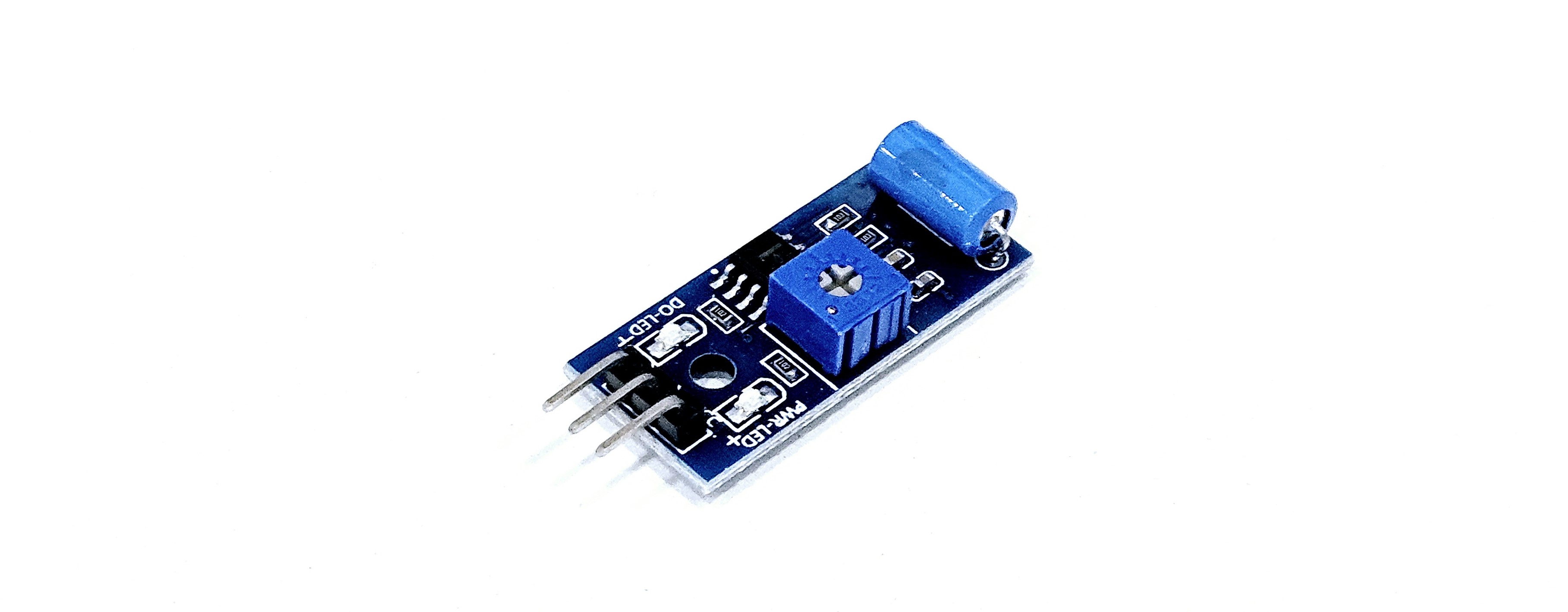
Overview
The SW-420 sensor is a vibration detection sensor primarily used for detecting vibrations or shocks. This sensor can be used with microcontrollers such as Arduino for various projects.
1. Vibration Detection Structure
It uses a mechanical switch that contains a metal ball inside. The metal ball is positioned between two electrodes within the sensor, and when external vibrations or shocks occur, the ball moves to make or break contact between the electrodes.
2. Operating Principle
Normal State: When the sensor is in a stable state, the metal ball does not make contact between the electrodes, resulting in a LOW (0V) output signal. Vibration Detection: When vibrations occur externally, the metal ball moves and makes contact with the electrodes. At this point, the output signal changes to HIGH (5V). This signal is transmitted to a microcontroller like Arduino, indicating that a vibration has been detected.
3. Sensitivity Adjustment
The SW-420 sensor has a built-in variable resistor that allows for sensitivity adjustment. By adjusting this resistor, the strength of the vibrations detected by the sensor can be controlled. In other words, increasing the sensitivity allows for the detection of weaker vibrations, while decreasing it makes the sensor only respond to stronger vibrations.
Specifications
- Voltage Range: DC 3.3V ~ 5V
- Signal Type: Digital Output (HIGH/LOW)
- Output Voltage: Approximately 5V in HIGH state, 0V in LOW state
- PCB Size: Approximately 32mm x 14mm
Application Examples
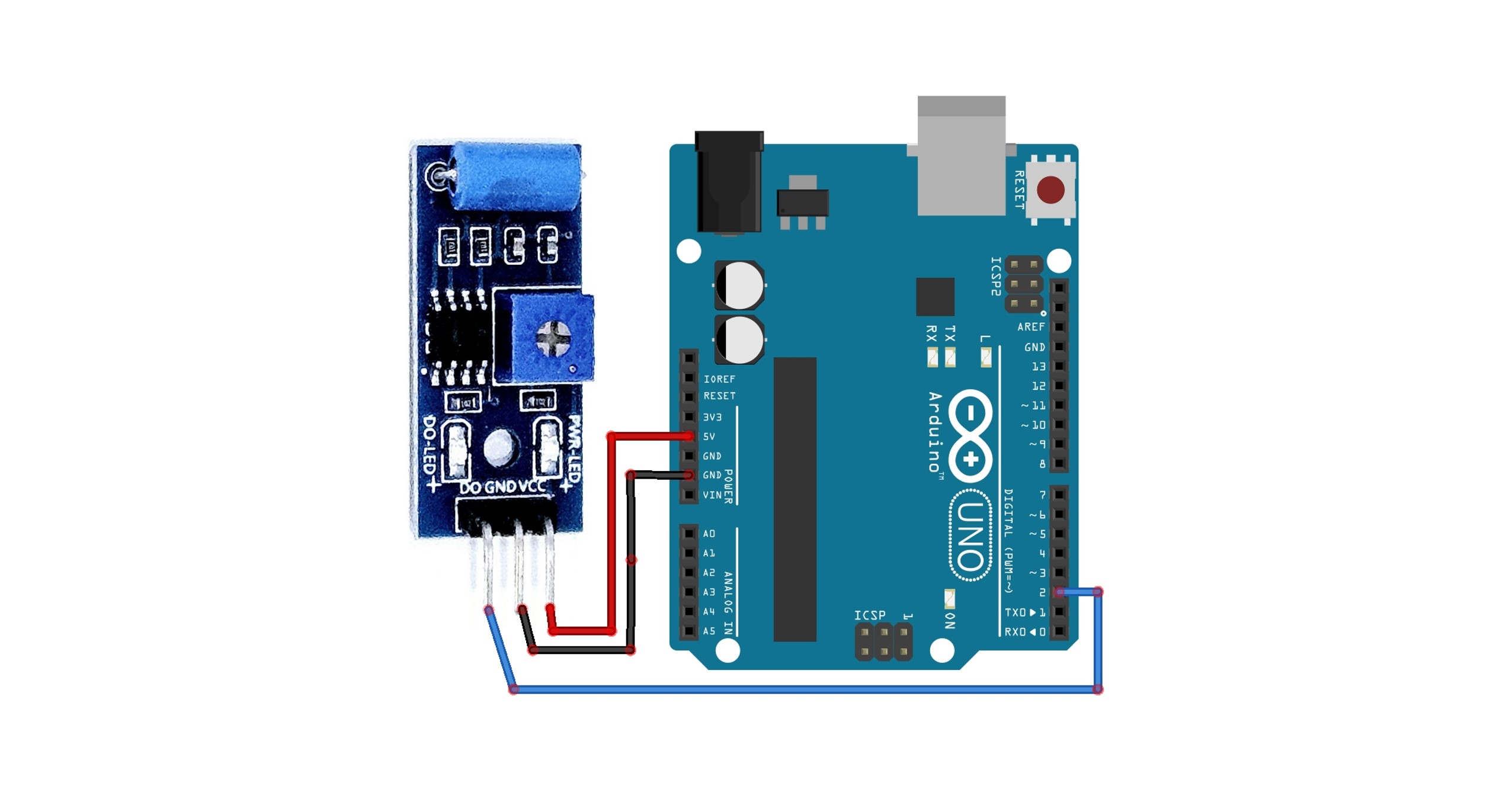
Basic Circuit Configuration
| Arduino | SW-420 Vibration Sensor |
|---|---|
| 5V | VCC |
| GND | GND |
| D2 | DO |

1. Detecting Vibration and Outputting to Serial Monitor
After constructing the basic circuit above, this is an example of checking whether the SW-420 vibration sensor detects vibrations by shaking it with your hand and observing the output on the serial monitor.
const int sensorPin = 2; // SW-420 OUT Pin Connect
int sensorValue = 0;

void setup() {
    Serial.begin(9600);
    pinMode(sensorPin, INPUT);
}

void loop() {
    sensorValue = digitalRead(sensorPin);
    if (sensorValue == HIGH) {
        Serial.println("Vibration Detection!");
    } else {
        Serial.println("No Vibration.");
    }
    delay(500);
}
Execution Result
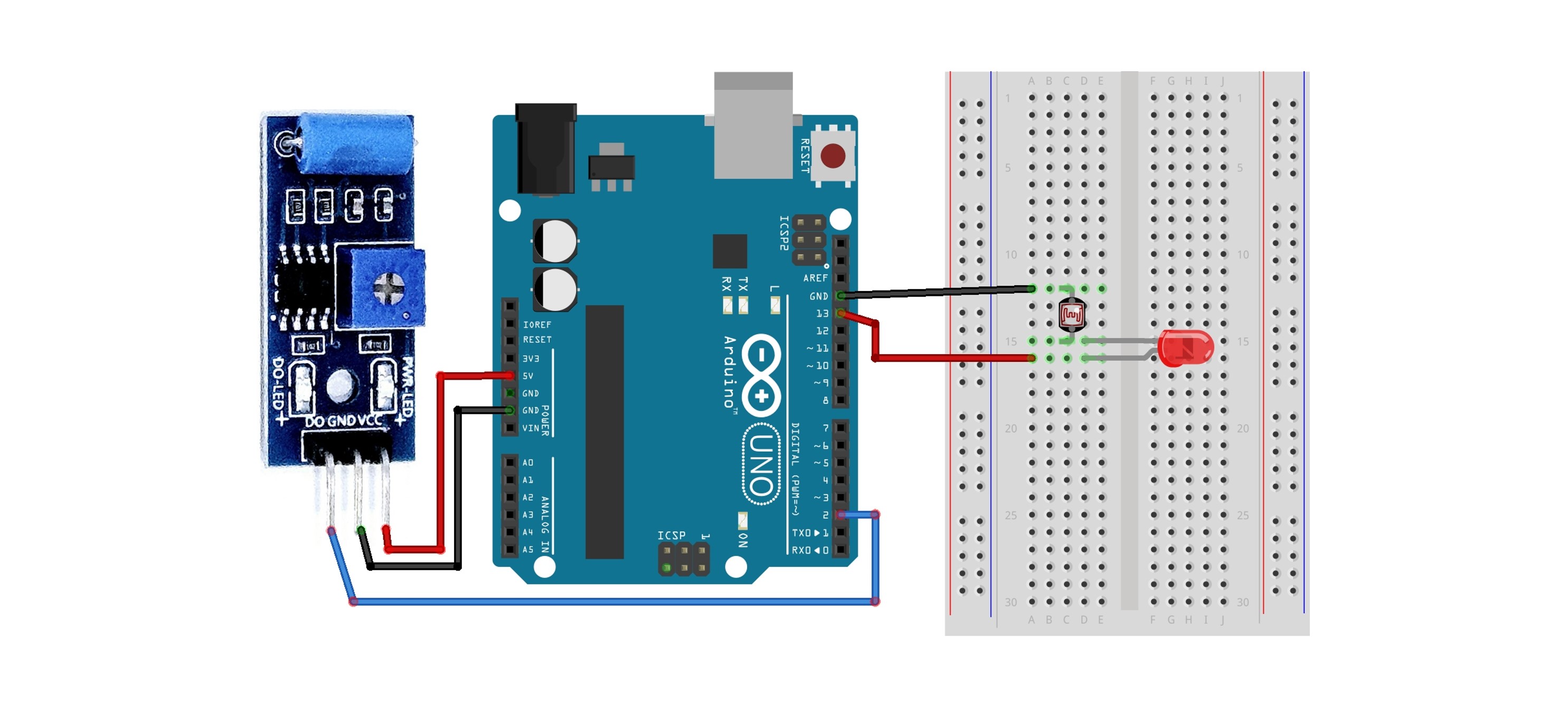
2. Using with LED
This is an example where the LED turns on when vibration is detected.
Circuit Configuration
Connect the shorter leg of the LED to a resistor, and then connect the resistor to the GND pin of the Arduino. Typically, a 100Ω or 220Ω resistor is used.
Connect the longer leg of the LED to the Arduino pin D13. For more detailed information about the LED, please refer to the LED(5mm) document.

Code
const int sensorPin = 2; // SW-420 OUT Pin
const int ledPin = 13;   // Built-in LED Pin
int sensorValue = 0;

void setup() {
    Serial.begin(9600);
    pinMode(sensorPin, INPUT);
    pinMode(ledPin, OUTPUT);
}

void loop() {
    sensorValue = digitalRead(sensorPin);
    if (sensorValue == HIGH) {
        Serial.println("Vibration Detection!");
        digitalWrite(ledPin, HIGH); // Turning on LED
    } else {
        Serial.println("No Vibration");
        digitalWrite(ledPin, LOW); // Turning off LED
    }
    delay(500);
}
Execution Results
When vibration is detected, the LED lights up, and the serial monitor will display results similar to those in Example 1.
