Tact Switch: 두 판 사이의 차이
(Created page with "{{#seo:|title=아두위키 : 아두이노 택트 스위치 가이드|title_mode=append|keywords=아두이노, 정보과학, 메이커학습, 수행평가, 택트 스위치, 아두이노 작품, 캡스톤작품, 아두이노 예제코드|description=아두이노와 호환되는 택트 스위치에 관한 통찰력 있는 가이드를 찾고 계신가요? 아두위키는 전자 부품을 제어하는 데 필요한 택트 스위치에 대한 심도 있는 정보를 제공...") |
잔글편집 요약 없음 |
||
| 1번째 줄: | 1번째 줄: | ||
{{#seo:|title= | {{#seo:|title=ArduWiki: Arduino Tact Switch Guide|title_mode=append|keywords=Arduino, Information Science, Maker Learning, Performance Evaluation, Tact Switch, Arduino Projects, Capstone Projects, Arduino Example Code|description=Introduces how to control tact switches with Arduino (basic information, circuit, example code). Can be used in Information Science and Maker classes.}} | ||
[[File:택트스위치 이미지.jpg|center|class=coders100]] | [[File:택트스위치 이미지.jpg|center|class=coders100]] | ||
A switch used to control circuits and other electronic components. | A switch used to control circuits and other electronic components. | ||
| 6번째 줄: | 6번째 줄: | ||
A button cap can be attached for use. | A button cap can be attached for use. | ||
== '''How to Use''' == | == '''How to Use''' == | ||
| 11번째 줄: | 12번째 줄: | ||
* [1, 3] and [2, 4] are connected together, and pressing the button connects all numbers. | * [1, 3] and [2, 4] are connected together, and pressing the button connects all numbers. | ||
== '''Connection and Example of Use''' == | == '''Connection and Example of Use''' == | ||
| 17번째 줄: | 19번째 줄: | ||
[[File:택트스위치 회로(코드x).png|center|class=coders100]] | [[File:택트스위치 회로(코드x).png|center|class=coders100]] | ||
=== Execution Result === | === Execution Result === | ||
2025년 3월 26일 (수) 21:53 기준 최신판

A switch used to control circuits and other electronic components.
It can be connected to a digital pin on Arduino and used as an input signal.
A button cap can be attached for use.
How to Use
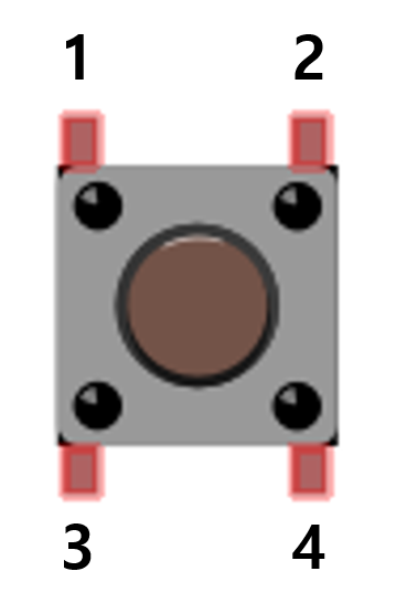
- [1, 3] and [2, 4] are connected together, and pressing the button connects all numbers.
Connection and Example of Use
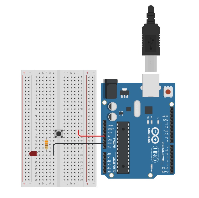
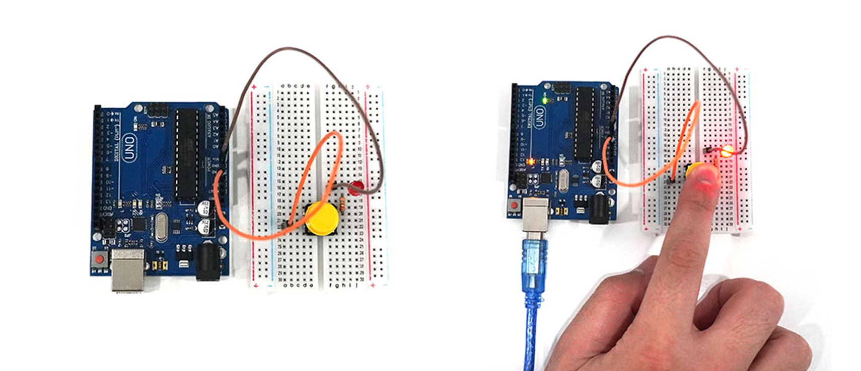
- When the switch is pressed, an LED lights up. No separate coding is provided.
Execution Result
Floating Phenomenon and Pull-up, Pull-down Resistors
Floating Phenomenon
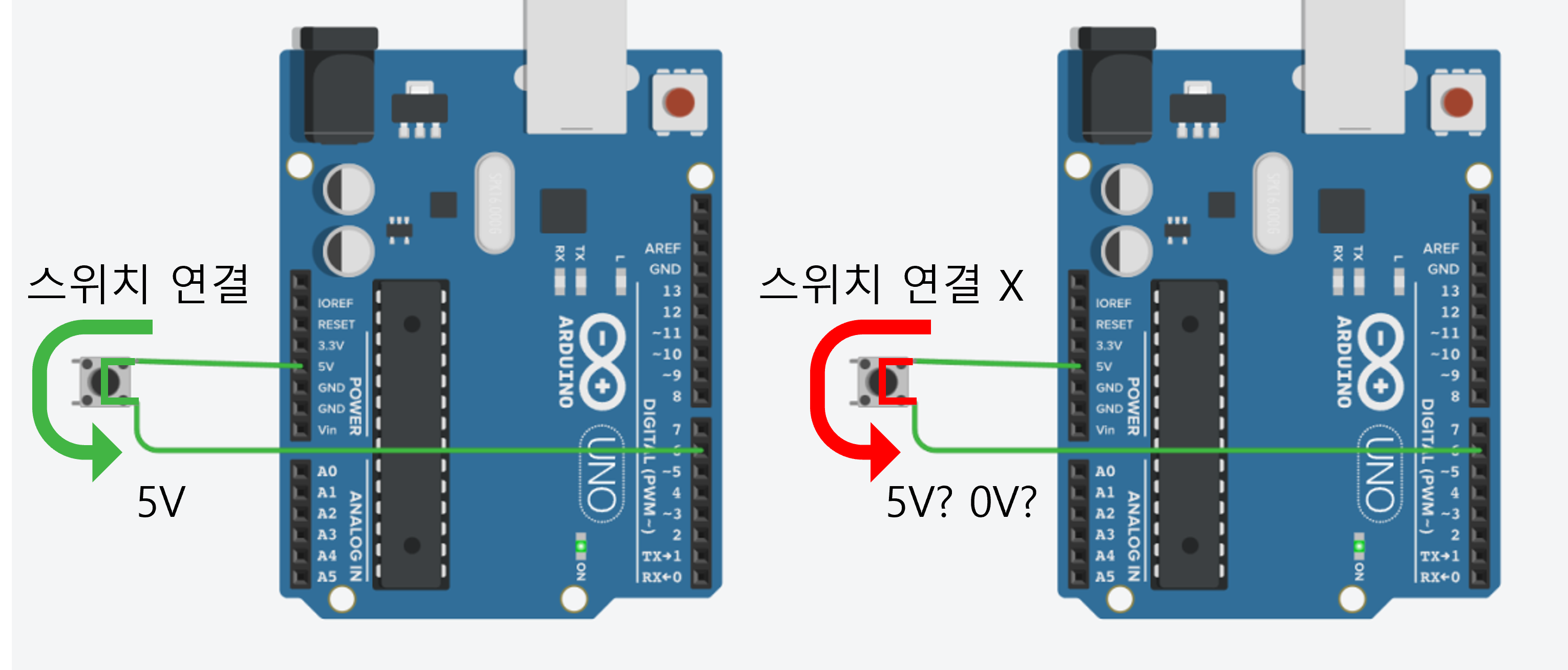
The floating phenomenon refers to the state where the input pin of a switch or button is not properly connected to any voltage.
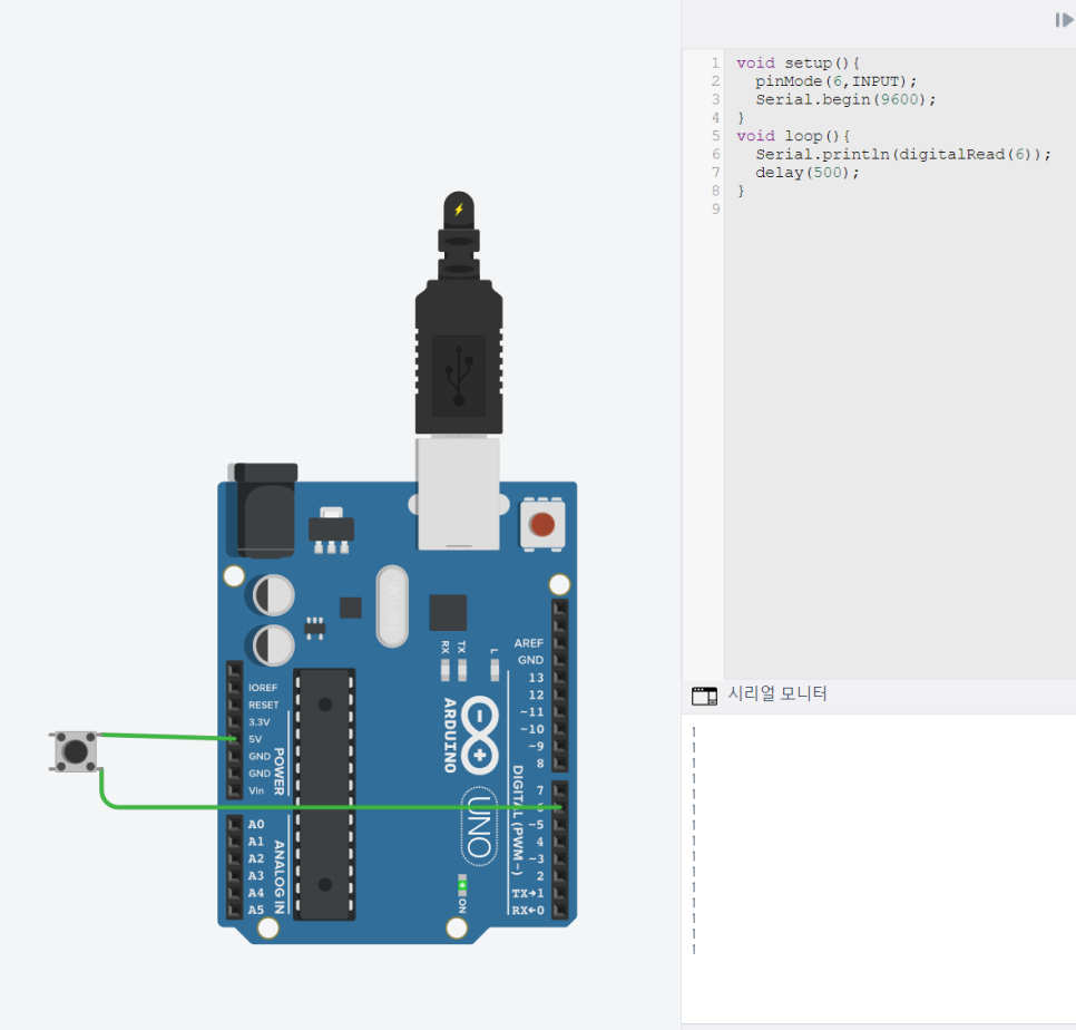
In the circuit above, when the switch is connected, a 5V (HIGH) signal is connected to pin 6.
However, when the switch is not connected, it's unclear whether pin 6 is HIGH or LOW.
Even without pressing the switch, the serial monitor may show the output of pin 6 as 1 (HIGH).
To solve this floating phenomenon, pull-up or pull-down resistors are needed.
Pull-up Resistor
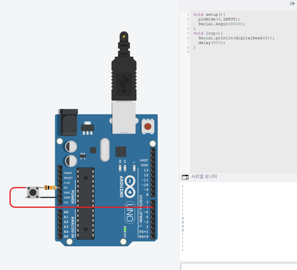
A resistor is added between the input pin and 5V.
When the switch is open, it remains 1 (HIGH), and when the switch is closed, it is shorted to GND, maintaining 0 (LOW).
Pull-down Resistor
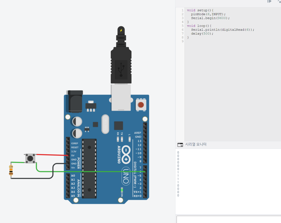
A resistor is added between the input pin and GND.
When the switch is open, it is shorted to GND, maintaining 0 (LOW), and when the switch is closed, it remains 1 (HIGH).
Arduino Internal Pull-up Resistor (INPUT_PULLUP)
Arduino has a built-in pull-up resistor.
When setting the digital input pin mode, using 'INPUT_PULLUP' allows you to use the digital pin as a pull-up resistor without adding an external resistor.
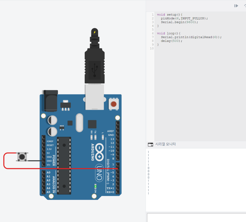
Setting pinMode to INPUT_PULLUP without adding a separate resistor yields the same result as using a pull-up resistor.