Buzzer En: 두 판 사이의 차이
잔글편집 요약 없음 |
잔글편집 요약 없음 |
||
| (같은 사용자의 중간 판 9개는 보이지 않습니다) | |||
| 1번째 줄: | 1번째 줄: | ||
{{#seo:|title= | {{#seo:|title=Arduwiki : Arduino Buzzer Guide|title_mode=append|keywords=Arduino, Information Science, Maker Learning, Performance Assessment, Buzzer, Arduino Project, Capstone Project, Arduino Example Code|description=This introduces how to control a buzzer with Arduino (basic information, circuit, example code). It can be used in Information Science and Maker classes.}} | ||
[[파일:부저 사진.jpg|가운데|class=coders100]] | [[파일:부저 사진.jpg|가운데|class=coders100]] | ||
== ''' | == '''Overview''' == | ||
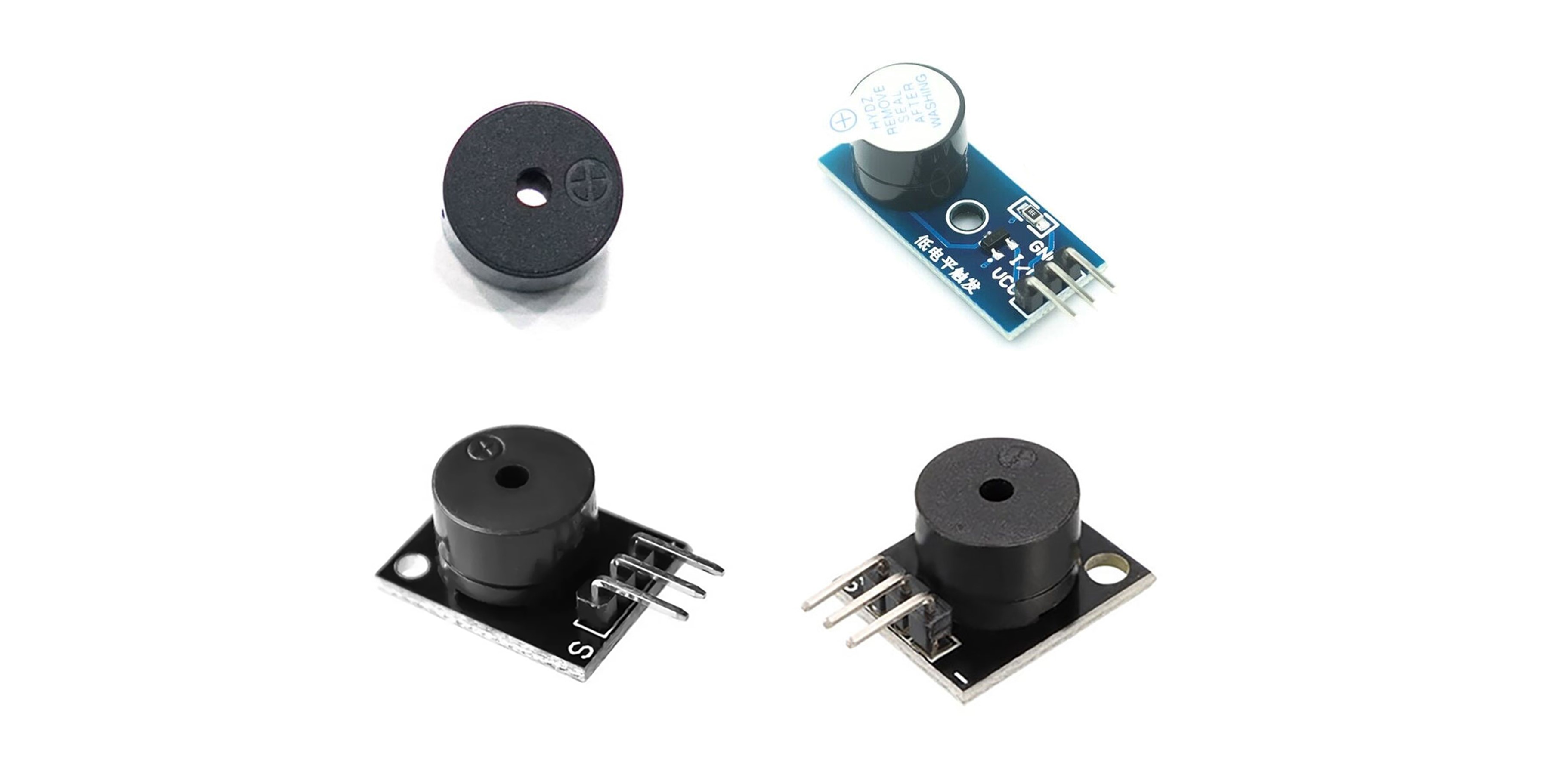
A buzzer is a device that generates sound and is used in various projects with microcontroller boards like Arduino to play alarm sounds, warning sounds, music, etc. Buzzers are mainly divided into Active Buzzers and Passive Buzzers. | |||
== ''' | == '''Active Buzzer and Passive Buzzer''' == | ||
=== | === Active Buzzer === | ||
The active buzzer has an internal oscillation circuit that generates sound automatically when powered. It is easy to control and is mainly used to produce a sound at a constant frequency (without adjusting the pitch). | |||
* ''' | * '''Simple Control''' : It generates sound just by turning the power on and off. | ||
* ''' | * '''Constant Frequency''' : It only produces sound at a specific frequency. | ||
=== | === Passive Buzzer === | ||
Unlike the active buzzer, which generates sound automatically when powered, a passive buzzer requires frequency control to produce sound. It can generate sounds of various frequencies using PWM (Pulse Width Modulation) signals, making it useful for playing melodies or various tones. | |||
* ''' | * '''Complex Control''' : The frequency must be controlled externally or through software. | ||
* ''' | * '''Various Frequencies''' : It can produce sounds of various frequencies. | ||
=== | === Distinction between Active and Passive Buzzers === | ||
It can be difficult to distinguish between active and passive buzzers based on their appearance. Instead, they can be differentiated through a simple test. | |||
==== 1. | ==== 1. Labels and Markings ==== | ||
This is a method of distinguishing based on appearance, but it may not be a definitive method as labeling can vary by product. | |||
* ''' | * '''Active Buzzer''' : It usually has a label indicating "Active" or a specific frequency (e.g., "5V 12kHz"). | ||
* ''' | * '''Passive Buzzer''' : It often does not have a label indicating "Passive" or any frequency. | ||
==== 2. Testing ==== | |||
The most certain method is to set up a simple circuit and differentiate them through testing. | |||
* '''Active Buzzer''' : It produces sound immediately when power is connected. | |||
* '''Passive Buzzer''' : It does not produce sound when power is connected, and sound is generated only when a frequency signal is input. | |||
== '''Circuit Configuration''' == | |||
The form of the buzzer may vary depending on the product, but the circuit is configured based on the same principle. | |||
== | === When there are 2 Pins === | ||
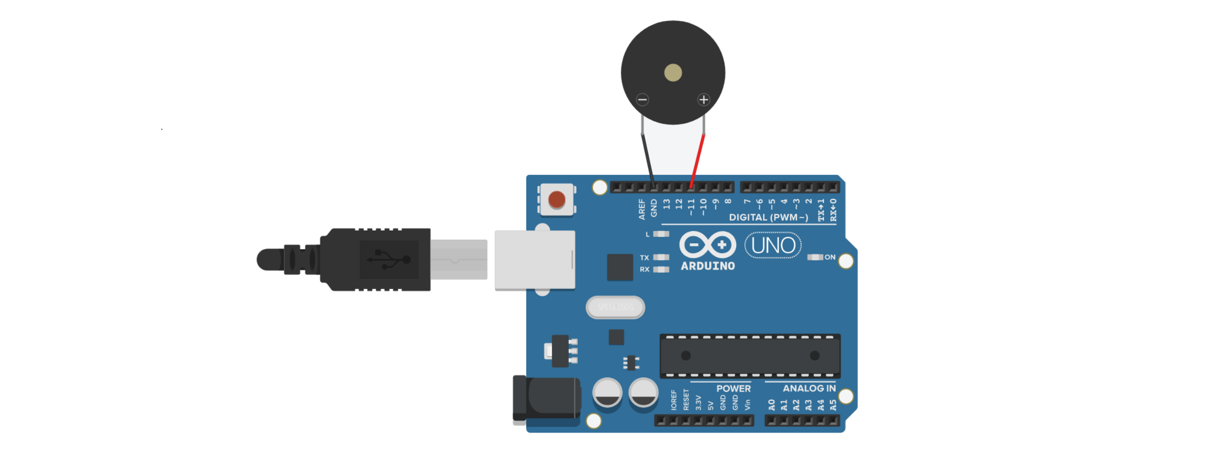
Connect the + terminal of the buzzer to a digital pin on the Arduino. | |||
Connect the - terminal of the buzzer to the GND of the Arduino. | |||
[[파일:수동부저 회로.png|가운데|class=coders100]] | [[파일:수동부저 회로.png|가운데|class=coders100]] | ||
=== When there are 3 Pins === | |||
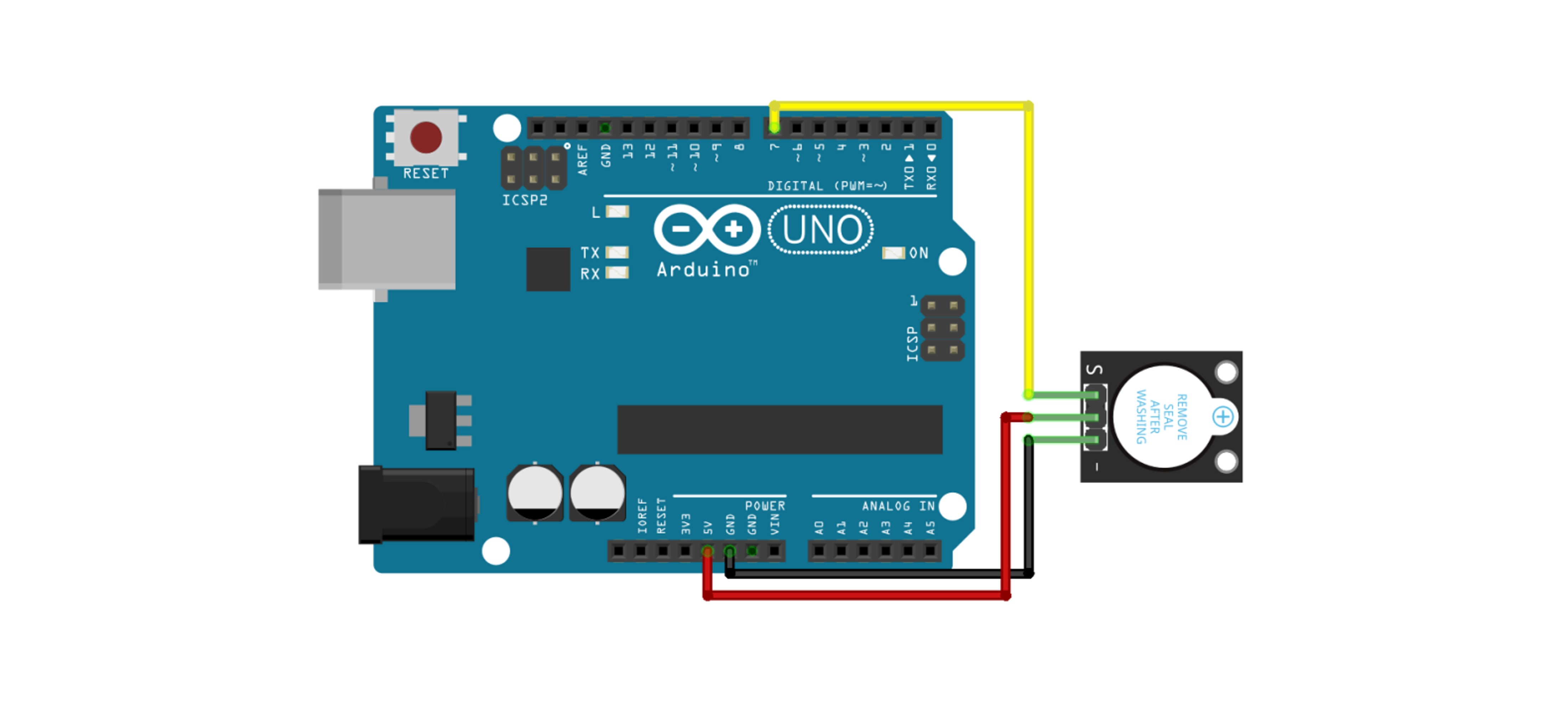
= | Connect the + terminal (or VCC) of the buzzer to the 5V pin on the Arduino. | ||
Connect the - terminal of the buzzer to the GND of the Arduino. | |||
Connect the digital pin terminal of the buzzer to a digital pin you will use on the Arduino. '''※ If the model is different from the photo below, the pin positions may vary, so be sure to check the connections carefully.''' | |||
[[파일:부저 3핀 회로.jpg|가운데|class=coders100]] | |||
== '''Usage Example''' == | |||
''' | |||
== | === 1. Controlling the Active Buzzer === | ||
This is an example of the active buzzer ringing 3 times. | |||
==== 1-1. | ==== 1-1. Circuit Configuration ==== | ||
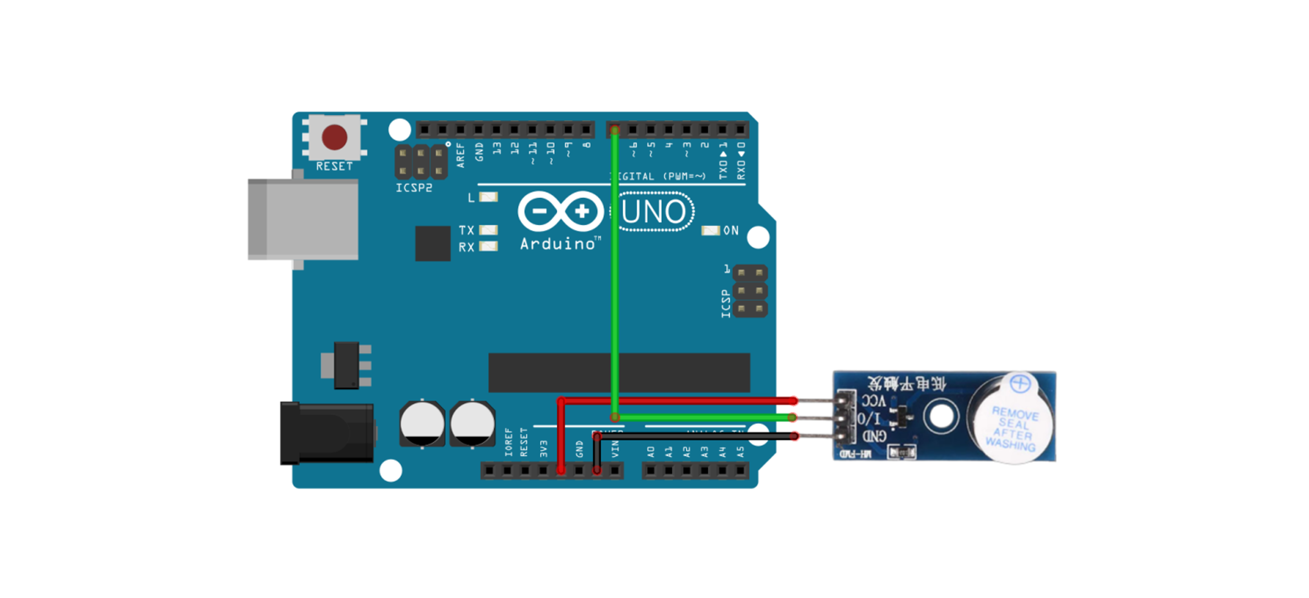
The image below shows an example using a product with 3 pins, but if you are using a product with 2 pins, please refer to the hardware connection section above for wiring. | |||
[[파일:능동부저 예제1 회로.png|가운데|class=coders100]] | |||
==== 1-2. | ==== 1-2. Code ==== | ||
<syntaxhighlight lang="c++" line="1"> | <syntaxhighlight lang="c++" line="1"> | ||
const int iopin = 7; | const int iopin = 7; | ||
| 85번째 줄: | 86번째 줄: | ||
==== 1-3. | ==== 1-3. Execution Result ==== | ||
<div class="coders70"> | <div class="coders70"> | ||
<youtube> Ow31hQcIxts </youtube> | <youtube> Ow31hQcIxts </youtube> | ||
| 91번째 줄: | 92번째 줄: | ||
=== 2. | === 2. Mixed Use of Active Buzzer and [[Tact Switch|Tact Switch]] === | ||
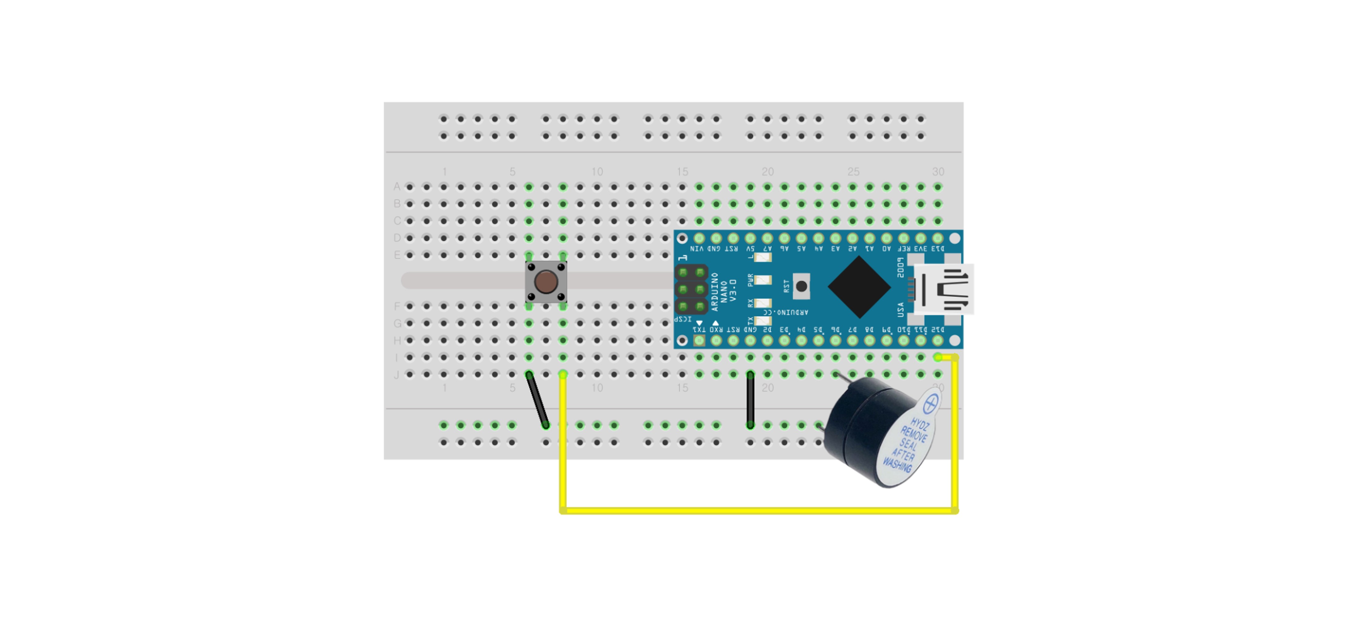
This example demonstrates how the active buzzer produces sound when the tact switch is pressed. | |||
==== 2-1. | ==== 2-1. Circuit Configuration ==== | ||
In this example, the INPUT_PULLUP resistor is used when connecting the tact switch. | |||
PULLUP, PULLDOWN, INPUT_PULLUP | For a detailed explanation of PULLUP, PULLDOWN, and INPUT_PULLUP resistors, please refer to the [[택트 스위치(Tact Switch)|택트 스위치]] document. | ||
[[파일:부저 예제1 회로.jpg|가운데|class=coders100]] | [[파일:부저 예제1 회로.jpg|가운데|class=coders100]] | ||
==== 2-2. | ==== 2-2. Code ==== | ||
<syntaxhighlight lang="c++" line="1"> | <syntaxhighlight lang="c++" line="1"> | ||
#define buzzer 6 | #define buzzer 6 | ||
| 123번째 줄: | 124번째 줄: | ||
==== 2-3. | ==== 2-3. Execution Result ==== | ||
<div class="coders70"> | <div class="coders70"> | ||
<youtube> T7I3b59x0QA </youtube> | <youtube> T7I3b59x0QA </youtube> | ||
| 129번째 줄: | 130번째 줄: | ||
=== 3. | === 3. Playing Musical Notes with Passive Buzzer Control === | ||
Unlike the active buzzer, the passive buzzer can express different tones by controlling the frequency. | |||
This is an example of playing the Do-Re-Mi-Fa-Sol-La-Si-Do scale in order. | |||
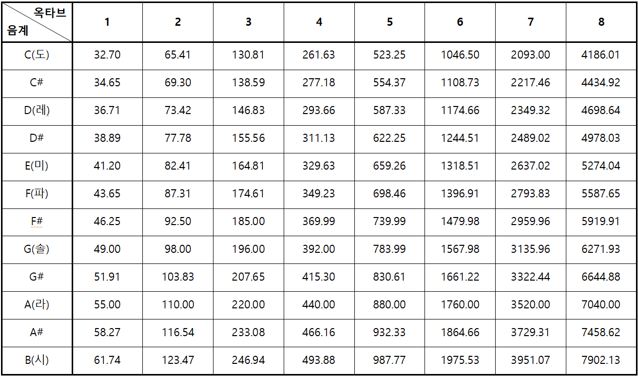
==== Reference Material: Standard Frequencies for Octaves and Notes ==== | |||
[[파일:옥타브 및 음계별 표준 주파수.png|가운데|class=coders100]] | [[파일:옥타브 및 음계별 표준 주파수.png|가운데|class=coders100]] | ||
==== 3-1. | ==== 3-1. Circuit Configuration ==== | ||
Please refer to the circuit in the hardware connection tab. | |||
==== 3-2. | ==== 3-2. Code ==== | ||
<syntaxhighlight lang="c++" line="1"> | <syntaxhighlight lang="c++" line="1"> | ||
#define buzzer 11 | #define buzzer 11 | ||
int numTones = 8; | int numTones = 8; | ||
//순서대로 ( | //순서대로 (4th Octave Do, 4th Octave Re, 4th Octave Mi, 4th Octave Fa, 4th Octave Sol, 4th Octave La, 4th Octave Si, 5th Octave Do) | ||
double tones[] = { 261.6256, 293.6648, 329.6276, 349.2282, 391.9954, 440, 493.8833, 523.2511 }; | double tones[] = { 261.6256, 293.6648, 329.6276, 349.2282, 391.9954, 440, 493.8833, 523.2511 }; | ||
| 163번째 줄: | 165번째 줄: | ||
for (int i = 0; i < numTones; i++) | for (int i = 0; i < numTones; i++) | ||
{ | { | ||
//tone( | //tone(Pin number, Frequency)로 사용합니다. | ||
tone(buzzer, tones[i]); | tone(buzzer, tones[i]); | ||
delay(500); | delay(500); | ||
} | } | ||
// | // If the noTone function is not used, the previously entered tone function will continue to execute, | ||
// | // so we use the noTone function to turn off the sound. | ||
noTone(buzzer); | noTone(buzzer); | ||
delay(500); | delay(500); | ||
| 177번째 줄: | 179번째 줄: | ||
==== 3-3. | ==== 3-3. Execution Result ==== | ||
<div class="coders70"> | <div class="coders70"> | ||
<youtube> vayYbS_Qjy0 </youtube> | <youtube> vayYbS_Qjy0 </youtube> | ||
| 183번째 줄: | 185번째 줄: | ||
=== 4. | === 4. Playing Melody with Passive Buzzer Control === | ||
This is an example of playing a simple melody with a passive buzzer. | |||
You can modify this example to play other melodies. | |||
==== 4-1. | ==== 4-1. Circuit Configuration ==== | ||
Please refer to the circuit in the hardware connection tab. | |||
==== 4-2. | ==== 4-2. Code ==== | ||
<syntaxhighlight lang="c++" line="1"> | <syntaxhighlight lang="c++" line="1"> | ||
#define buzzer 11 | #define buzzer 11 | ||
| 198번째 줄: | 201번째 줄: | ||
int numTones = 8; | int numTones = 8; | ||
double g_tones[] = { 195.9977, 220, 246.9417, 261.6256, 293.6648, 329.6276, 349.2282, 391.9954 }; | double g_tones[] = { 195.9977, 220, 246.9417, 261.6256, 293.6648, 329.6276, 349.2282, 391.9954 }; | ||
// | //Sol 0, La 1, Si 2, Do 3, Re 4, Mi 5, Fa 6, Sol 7 | ||
int cnt = 0; | int cnt = 0; | ||
| 282번째 줄: | 285번째 줄: | ||
==== 4-3. Execution Result ==== | |||
Video attachment to be provided | |||
== ''' | == '''Other Usage Examples''' == | ||
Buzzers can be used in various projects where sound is needed. | |||
'''Alarm System''': A system that emits a warning sound when certain conditions are met | |||
'''Timer''': A sound that indicates the passage of time | |||
'''Music Playback''': A device that plays simple melodies or sound effects | |||
'''Games''': Sound effects or victory/defeat notification sounds in games | |||
2025년 3월 27일 (목) 14:08 기준 최신판
Overview
A buzzer is a device that generates sound and is used in various projects with microcontroller boards like Arduino to play alarm sounds, warning sounds, music, etc. Buzzers are mainly divided into Active Buzzers and Passive Buzzers.
Active Buzzer and Passive Buzzer
Active Buzzer
The active buzzer has an internal oscillation circuit that generates sound automatically when powered. It is easy to control and is mainly used to produce a sound at a constant frequency (without adjusting the pitch).
- Simple Control : It generates sound just by turning the power on and off.
- Constant Frequency : It only produces sound at a specific frequency.
Passive Buzzer
Unlike the active buzzer, which generates sound automatically when powered, a passive buzzer requires frequency control to produce sound. It can generate sounds of various frequencies using PWM (Pulse Width Modulation) signals, making it useful for playing melodies or various tones.
- Complex Control : The frequency must be controlled externally or through software.
- Various Frequencies : It can produce sounds of various frequencies.
Distinction between Active and Passive Buzzers
It can be difficult to distinguish between active and passive buzzers based on their appearance. Instead, they can be differentiated through a simple test.
1. Labels and Markings
This is a method of distinguishing based on appearance, but it may not be a definitive method as labeling can vary by product.
- Active Buzzer : It usually has a label indicating "Active" or a specific frequency (e.g., "5V 12kHz").
- Passive Buzzer : It often does not have a label indicating "Passive" or any frequency.
2. Testing
The most certain method is to set up a simple circuit and differentiate them through testing.
- Active Buzzer : It produces sound immediately when power is connected.
- Passive Buzzer : It does not produce sound when power is connected, and sound is generated only when a frequency signal is input.
Circuit Configuration
The form of the buzzer may vary depending on the product, but the circuit is configured based on the same principle.
When there are 2 Pins
Connect the + terminal of the buzzer to a digital pin on the Arduino. Connect the - terminal of the buzzer to the GND of the Arduino.
When there are 3 Pins
Connect the + terminal (or VCC) of the buzzer to the 5V pin on the Arduino. Connect the - terminal of the buzzer to the GND of the Arduino. Connect the digital pin terminal of the buzzer to a digital pin you will use on the Arduino. ※ If the model is different from the photo below, the pin positions may vary, so be sure to check the connections carefully.
Usage Example
1. Controlling the Active Buzzer
This is an example of the active buzzer ringing 3 times.
1-1. Circuit Configuration
The image below shows an example using a product with 3 pins, but if you are using a product with 2 pins, please refer to the hardware connection section above for wiring.
1-2. Code
const int iopin = 7;

void setup() {
  pinMode(iopin, OUTPUT);
  digitalWrite(iopin, HIGH);
  for (int i = 0; i < 3; i++) {
    digitalWrite(iopin, LOW);
    delay(500);
    digitalWrite(iopin, HIGH);
    delay(500);
  }
}

void loop() {
  delay(10);
}
1-3. Execution Result
2. Mixed Use of Active Buzzer and Tact Switch
This example demonstrates how the active buzzer produces sound when the tact switch is pressed.
2-1. Circuit Configuration
In this example, the INPUT_PULLUP resistor is used when connecting the tact switch.
For a detailed explanation of PULLUP, PULLDOWN, and INPUT_PULLUP resistors, please refer to the 택트 스위치 document.
2-2. Code
#define buzzer 6
#define btn 12

void setup() {
  pinMode(buzzer, OUTPUT);
  pinMode(btn, INPUT_PULLUP);
}

void loop() {
  if (!digitalRead(btn)) {
    for (int i = 0; i < 6; i++) {
      digitalWrite(buzzer, !digitalRead(buzzer));
      delay(100);
    }
  }
  delay(10);
}
2-3. Execution Result
3. Playing Musical Notes with Passive Buzzer Control
Unlike the active buzzer, the passive buzzer can express different tones by controlling the frequency.
This is an example of playing the Do-Re-Mi-Fa-Sol-La-Si-Do scale in order.
Reference Material: Standard Frequencies for Octaves and Notes
3-1. Circuit Configuration
Please refer to the circuit in the hardware connection tab.
3-2. Code
#define buzzer 11
int numTones = 8;

//순서대로 (4th Octave Do, 4th Octave Re, 4th Octave Mi, 4th Octave Fa, 4th Octave Sol, 4th Octave La, 4th Octave Si, 5th Octave Do)
double tones[] = { 261.6256, 293.6648, 329.6276, 349.2282, 391.9954, 440, 493.8833, 523.2511 };

int cnt = 0;

void setup()
{

}

void loop()
{
    if (cnt == 0)
    {
        for (int i = 0; i < numTones; i++)
        {
            //tone(Pin number, Frequency)로 사용합니다.
            tone(buzzer, tones[i]);
            delay(500);
        }
        // If the noTone function is not used, the previously entered tone function will continue to execute,
        // so we use the noTone function to turn off the sound.
        noTone(buzzer);
        delay(500);
        cnt++;
    }
}
3-3. Execution Result
4. Playing Melody with Passive Buzzer Control
This is an example of playing a simple melody with a passive buzzer.
You can modify this example to play other melodies.
4-1. Circuit Configuration
Please refer to the circuit in the hardware connection tab.
4-2. Code
#define buzzer 11

int numTones = 8;
double g_tones[] = { 195.9977, 220, 246.9417, 261.6256, 293.6648, 329.6276, 349.2282, 391.9954 };
//Sol 0, La 1, Si 2, Do 3, Re 4, Mi 5, Fa 6, Sol 7
int cnt = 0;

void setup()
{

}

void loop()
{
    if (cnt == 0)
    {
        tone(buzzer, g_tones[0]);
        delay(250 * 2);
        noTone(buzzer);
        tone(buzzer, g_tones[3]);
        delay(250 * 2);
        noTone(buzzer);
        tone(buzzer, g_tones[2]);
        delay(125 * 2);
        noTone(buzzer);
        tone(buzzer, g_tones[3]);
        delay(125 * 2);
        noTone(buzzer);
        tone(buzzer, g_tones[4]);
        delay(250 * 2);
        noTone(buzzer);
        tone(buzzer, g_tones[3]);
        delay(125 * 2);
        noTone(buzzer);
        tone(buzzer, g_tones[4]);
        delay(125 * 2);
        noTone(buzzer);
        tone(buzzer, g_tones[5]);
        delay(125 * 2);
        noTone(buzzer);
        tone(buzzer, g_tones[5]);
        delay(125 * 2);
        noTone(buzzer);
        tone(buzzer, g_tones[6]);
        delay(125 * 2);
        noTone(buzzer);
        tone(buzzer, g_tones[5]);
        delay(125 * 2);
        noTone(buzzer);
        tone(buzzer, g_tones[1]);
        delay(250 * 2);
        noTone(buzzer);
        tone(buzzer, g_tones[4]);
        delay(125 * 2);
        noTone(buzzer);
        tone(buzzer, g_tones[4]);
        delay(125 * 2);
        noTone(buzzer);
        tone(buzzer, g_tones[3]);
        delay(250 * 2);
        noTone(buzzer);
        tone(buzzer, g_tones[3]);
        delay(125 * 2);
        noTone(buzzer);
        tone(buzzer, g_tones[3]);
        delay(125 * 2);
        noTone(buzzer);
        tone(buzzer, g_tones[2]);
        delay(250 * 2);
        noTone(buzzer);
        tone(buzzer, g_tones[1]);
        delay(125 * 2);
        noTone(buzzer);
        tone(buzzer, g_tones[2]);
        delay(125 * 2);
        noTone(buzzer);
        tone(buzzer, g_tones[3]);
        delay(250 * 4);
        noTone(buzzer);
        cnt++;
    }else
    {

    }
}
4-3. Execution Result
Video attachment to be provided
Other Usage Examples
Buzzers can be used in various projects where sound is needed.
Alarm System: A system that emits a warning sound when certain conditions are met Timer: A sound that indicates the passage of time Music Playback: A device that plays simple melodies or sound effects Games: Sound effects or victory/defeat notification sounds in games