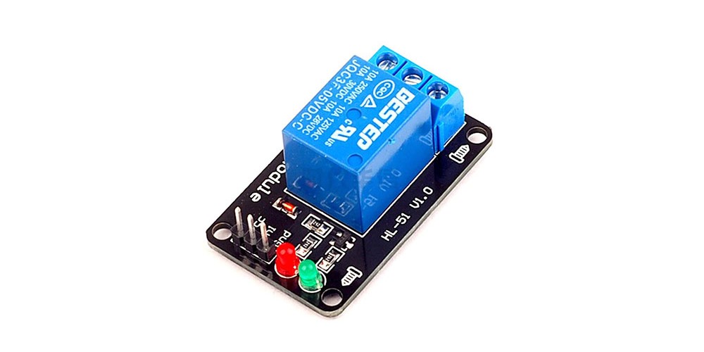
Relay Module En

It's a 1-Channel Relay Module.
The switch changes when at a LOW level. It comes equipped with holes for mounting and an LED for current status indication.
Specifications
- Operating Voltage: 5V
- Recommended for low-power use similar to Arduino level (Not recommended for connecting to household power (220V))
Example Required Hardware
- Arduino board
- Relay
- Jumper cables
- Red and Green LEDs
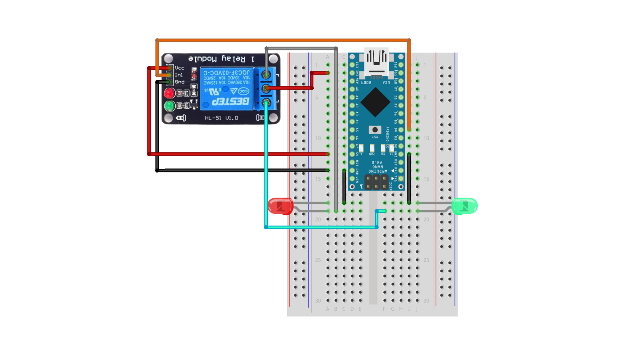
Connection
| Arduino | Relay | Red LED | Green LED |
| 5V | VCC | ||
| 3.3V | 2 | ||
| GND | GND | - | - |
| D4 | In1 | ||
| 1 | + | ||
| 3 | + |

Example Code
This example illustrates how to verify relay control with LEDs connected.
const int relay = 4;

void setup() {
  pinMode(relay, OUTPUT);
  digitalWrite(relay, HIGH);
}

void loop() {
  for (int i = 0; i < 3; i++) {
    digitalWrite(relay, LOW);
    delay(500);
    digitalWrite(relay, HIGH);
    delay(500);
  }
  delay(9999);
}
Execution Result
Please check the link for the operation video.