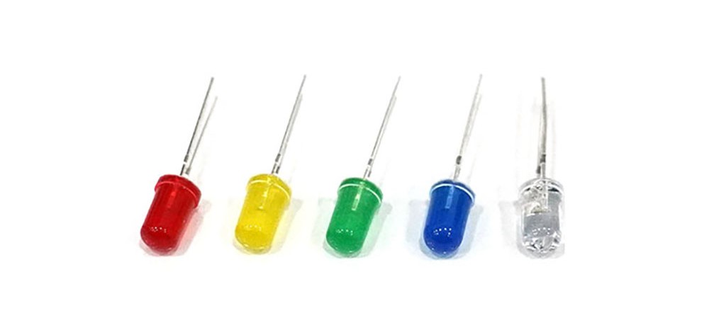
LED 5mm

Apply a constant voltage to emit light.
The longer leg is the positive (+) terminal and the shorter one is the negative (-) terminal, so caution is needed when connecting.
Be careful not to supply a voltage higher than the maximum voltage of the product.
Specifications
These are the specifications of the LED discussed in the text. Specifications may vary slightly depending on the manufacturer and model.
| Color | Minimum Voltage[V] | Maximum Voltage[V] | Standard Current[mA] | Maximum Current[mA] |
| Red | 1.8 | 2.3 | 20 | 50 |
| Yellow | 2 | 2.8 | ||
| Green | 3 | 3.6 | ||
| Blue | 3.4 | 3.8 | ||
| White | 3.4 | 4 |
Required Hardware
- LED
- Arduino board
- Jumper cables
Connection
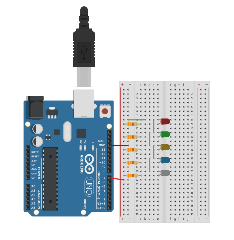
Connect the longer leg through a resistor to a digital pin, and the shorter leg to the Arduino's GND.
You can connect the long legs together to operate from a single digital pin as shown below, or set different digital pins for each LED if you want them to operate separately.
| Component | Connection to Arduino | Notes |
| LED(+) | Connected to Resistor | Resistor limits current to Protect LED |
| Resistor | Connected to D7 Pin | Recommended to use a resistor between 220Ω and 330Ω |
| LED(-) | Connected to GND |

Example Code
#define led 7 // Use pin 7
#define dly 1000

void setup() {
  pinMode(led, OUTPUT);
}

void loop() { // Code for turning on the LED for 1 second intervals
  digitalWrite(led, HIGH);
  delay(dly);
  digitalWrite(led, LOW);
  delay(dly);
}
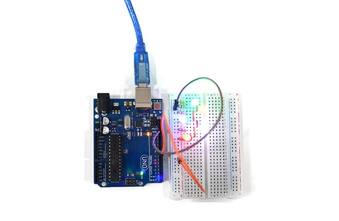
Execution Result
