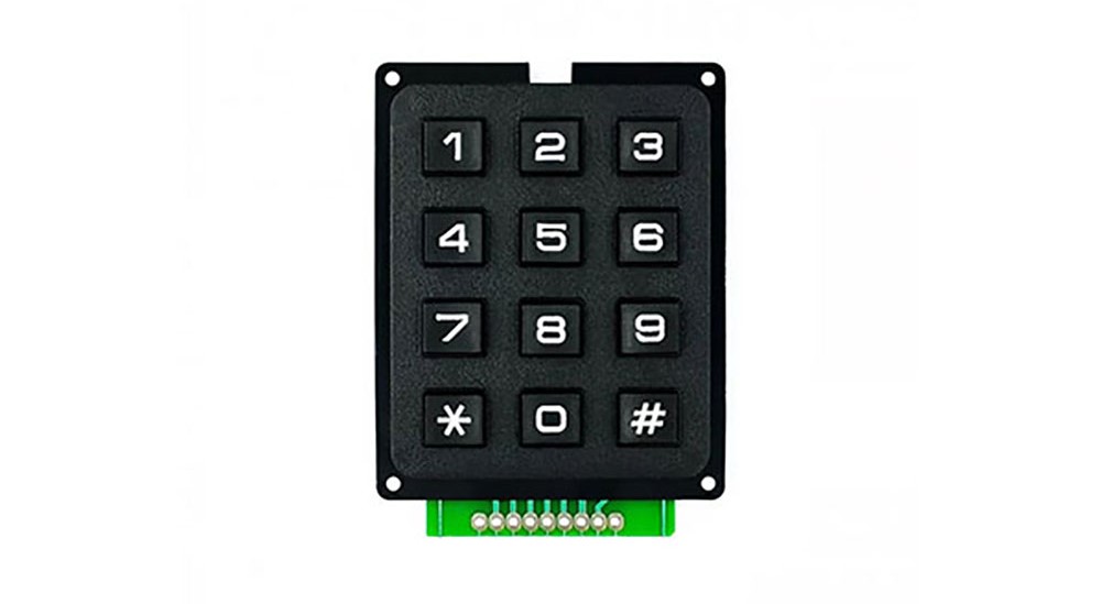
3x4 Matrix Keypad

It's a 3x4 numeric type keypad. The far-left and far-right pins are not used, leaving pins 1 to 7, starting from the left, for use.
You can check the pin numbers in the image provided.
[For example, pressing '1' on the keypad will output signals from pins 3 and 2.]
Specifications
- Operating Voltage: 3 ~ 5V
- Resistance: 10 ~ 150 ohms
Example Required Hardware
- Arduino board
- Jumper cables
- 3x4 keypad
Library
- Keypad by Mark Stanley, Alexander Brevig (installable via the Library Manager)
- Please refer to the Arduino library link for instructions on how to use the library.
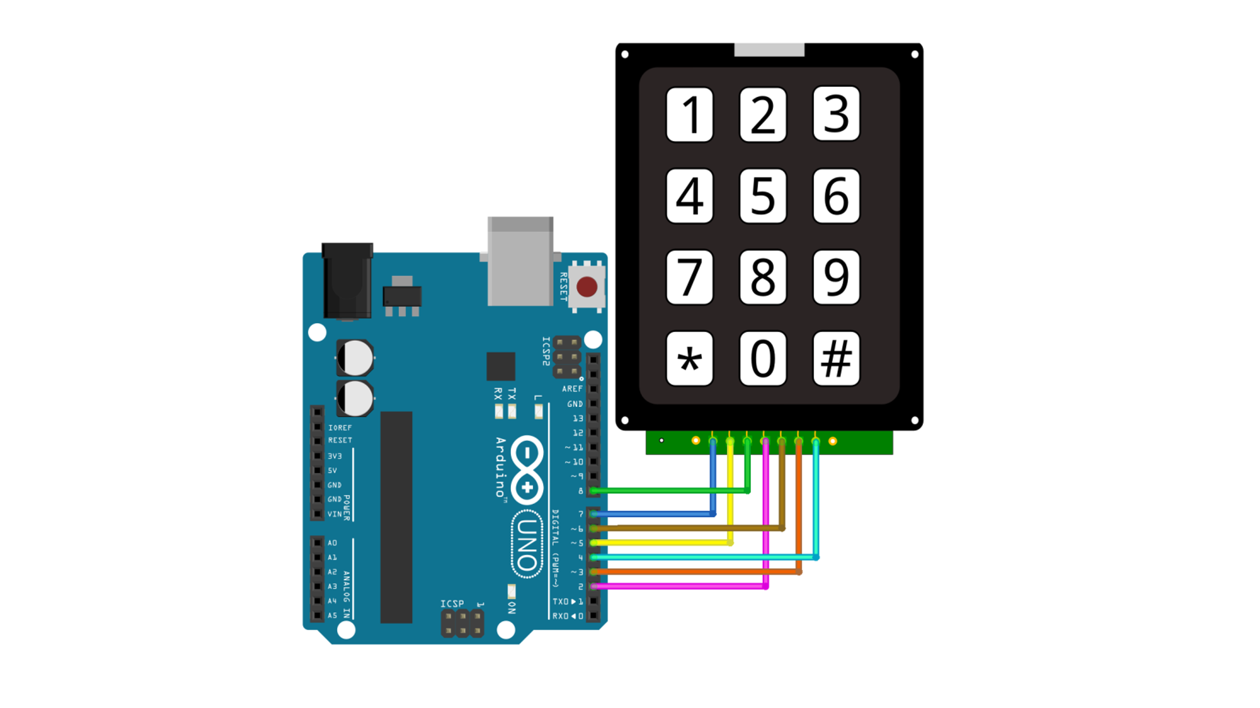
Connection
| keypad | Arduino | |||
| 1 | D7 | |||
| 2 | D5 | |||
| 3 | D8 | |||
| 4 | D2 | |||
| 5 | D6 | |||
| 6 | D3 | |||
| 7 | D4 | |||

example code
This code outputs to the serial monitor when a key on the keypad is pressed.
#include <Keypad.h>

const byte ROWS = 4;
const byte COLS = 3;

char keys[ROWS][COLS] = {
  { '1', '2', '3' },
  { '4', '5', '6' },
  { '7', '8', '9' },
  { '*', '0', '#' }
};

byte rowPins[ROWS] = { 5, 3, 4, 2 };
byte colPins[COLS] = { 8, 7, 6 };

Keypad keypad = Keypad(makeKeymap(keys), rowPins, colPins, ROWS, COLS);

void setup(){
  Serial.begin(9600);
  Serial.println("Serial start");
}

void loop(){
  char key = keypad.getKey();

  if(key != NO_KEY){
      Serial.print(key);
  }
}
Execution Result
