I2C OLED Module En
Overview
The Arduino OLED module is a display module with a small size and high resolution, suitable for various projects. Based on OLED (Organic Light Emitting Diode) technology, it provides excellent color and contrast.
OLED Operating Principle
Organic Material: OLED contains a thin layer of organic materials that emit light when an electric current passes through. Organic compounds have the property of emitting light when stimulated electrically. Electrodes: The OLED panel typically consists of two electrodes (anode and cathode). When electricity flows, the organic material releases electrons, and these electrons combine with holes to generate light.
SSD1306
The SSD1306 is a driver IC (integrated circuit) used to control OLED displays.
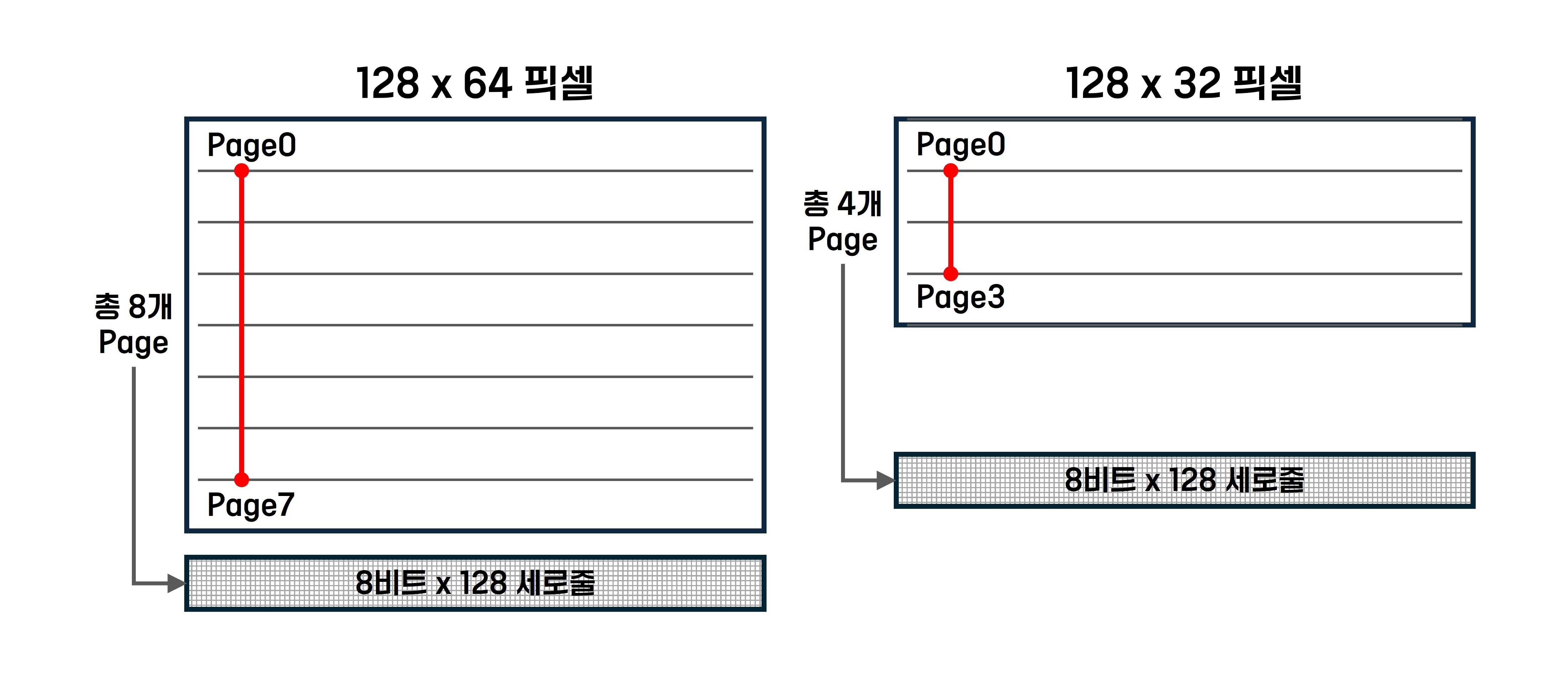
It contains 1KB of dedicated RAM for graphic display (GDDRAM), which is used to store the bit patterns to be displayed.
| List | Explanation |
|---|---|
| Memory capacity | 1KB (8192bit) |
| Number of Page | 8 page (Page 0-7) |
| Number of lines arranged vertically | 128 vertical lines (vertical line 0-127) |
| Bit Information | 8 bits per vertical line (bits 0-7) |
| Calculation | 8 pages x 128 vertical lines x 8 bits = 8192 bits = 1024 bytes (1KB) |
Specification
| List | Explanation |
|---|---|
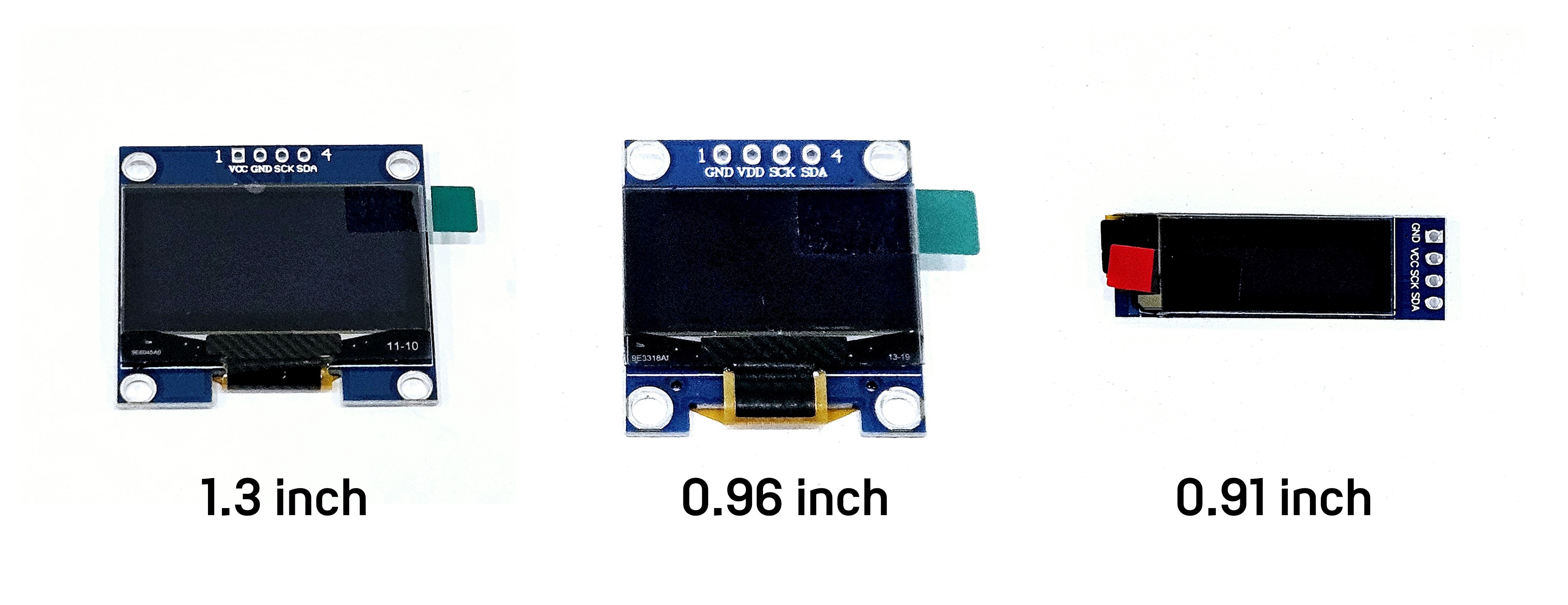
| Display Size | Various sizes such as 0.91inch, 0.96inch, 1.3inch, 2.42inch |
| Resolution | 128x64 pixels or 128x32 pixels |
| Display Type | OLED (Organic Light Emitting Diode) |
| Color | Black and White (White or Blue) |
| Interface | I2C (2 pins) |
| Voltage | 3.3V ~ 5V |
| Power Consumption | Standby Power: About 0.1mA, Maximum Power: About 20mA |
Application Examples
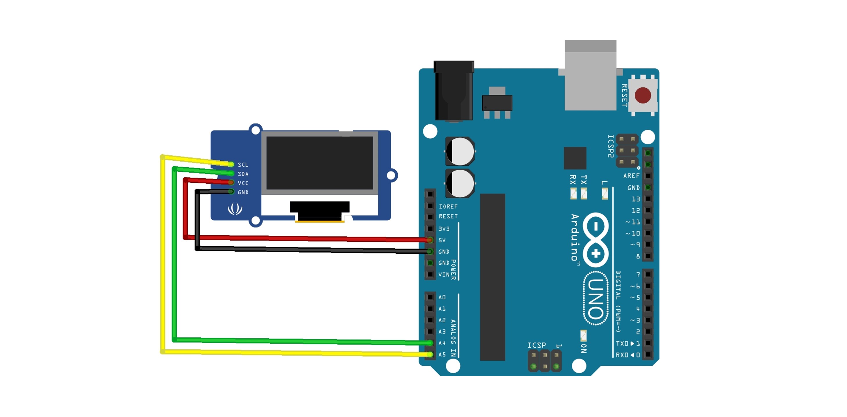
Circuit Configuration
| OLED module pin | Arduino Uno/Nano | Arduino Mega |
|---|---|---|
| VCC | 5V or 3.3V | 5V or 3.3V |
| GND | GND | GND |
| SCL | A5 | 21 |
| SDA | A4 | 22 |
Device Address Verification
This is the code used to find the address of devices connected to the I2C bus.
Before running the examples introduced below, please run the I2C Scanner first to check the address of the module.
#include <Wire.h>

void setup() {
  Serial.begin(9600);
  Wire.begin();
  Serial.println("I2C Scanner Start...");
}

void loop() {
  byte error, address;
  int nDevices = 0;

  Serial.println("I2C Device Scanning...");

  for (address = 1; address < 127; address++) {
    // Attempting to connect to the I2C device
    Wire.beginTransmission(address);
    error = Wire.endTransmission();

    if (error == 0) {
      Serial.print("Device found! Address: 0x");
      if (address < 16) {
        Serial.print("0");
      }
      Serial.print(address, HEX);
      Serial.println();
      nDevices++;
    } else if (error == 4) {
      Serial.print("Address 0x");
      Serial.print(address, HEX);
      Serial.println("error occurred!");
    }
  }

  if (nDevices == 0) {
    Serial.println("No I2C device found.");
  } else {
    Serial.println("Device scanning complete.");
  }

  delay(5000); // Wait for 5 seconds before scanning again.
}
실행 결과

Library
Please use the Adafruit SSD1306 library.
When installing SSD1306, please also click INSTALL ALL to install the required Adafruit BusIO and Adafruit GFX Library together.

1. Library Default Examples
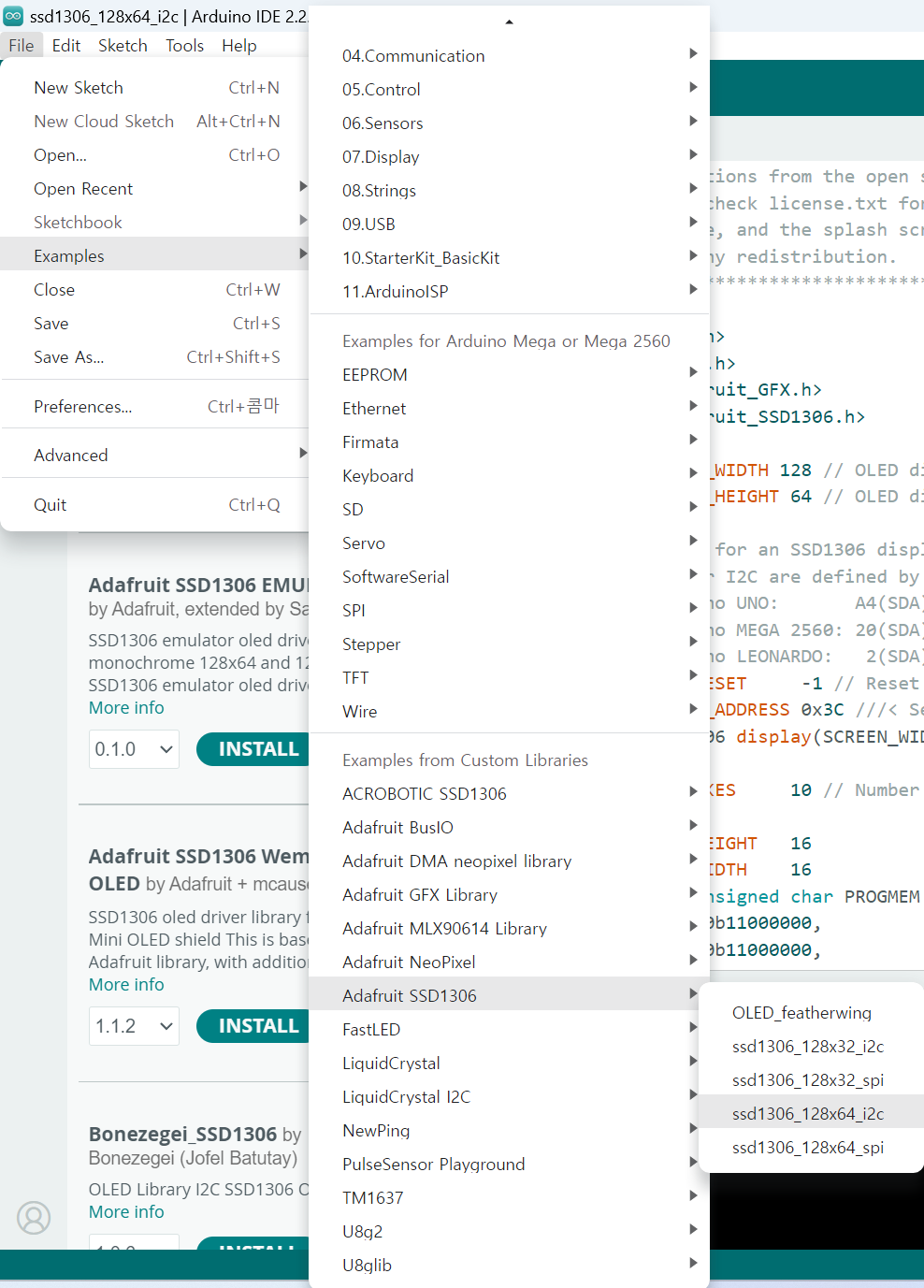
Click on File - Examples - Adafruit SSD1306 - ssd1306_128x64 i2c to open the example.
Please change the Address part in the example code to the device address confirmed earlier with the I2C Scanner.

Execution Result
2. Text Output
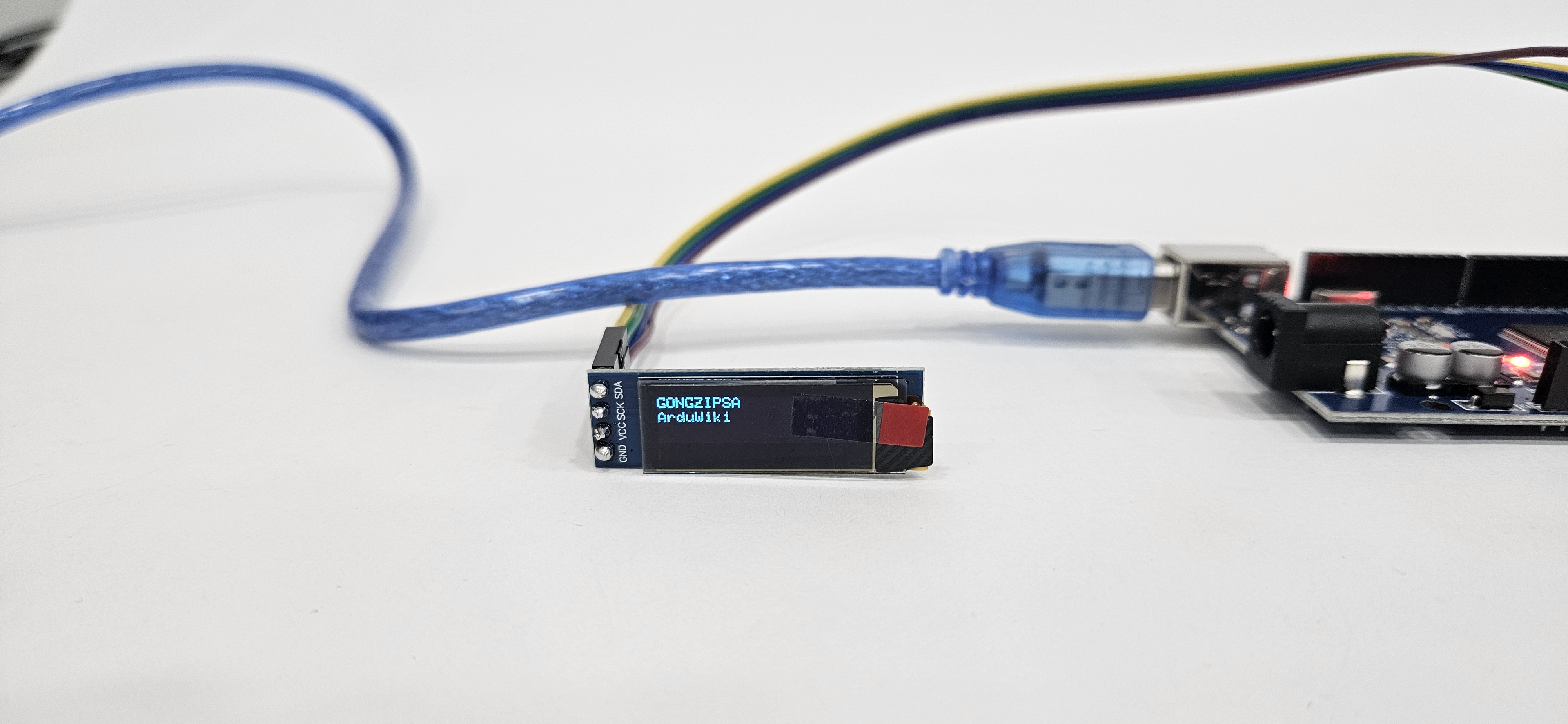
This is an example of printing simple text.
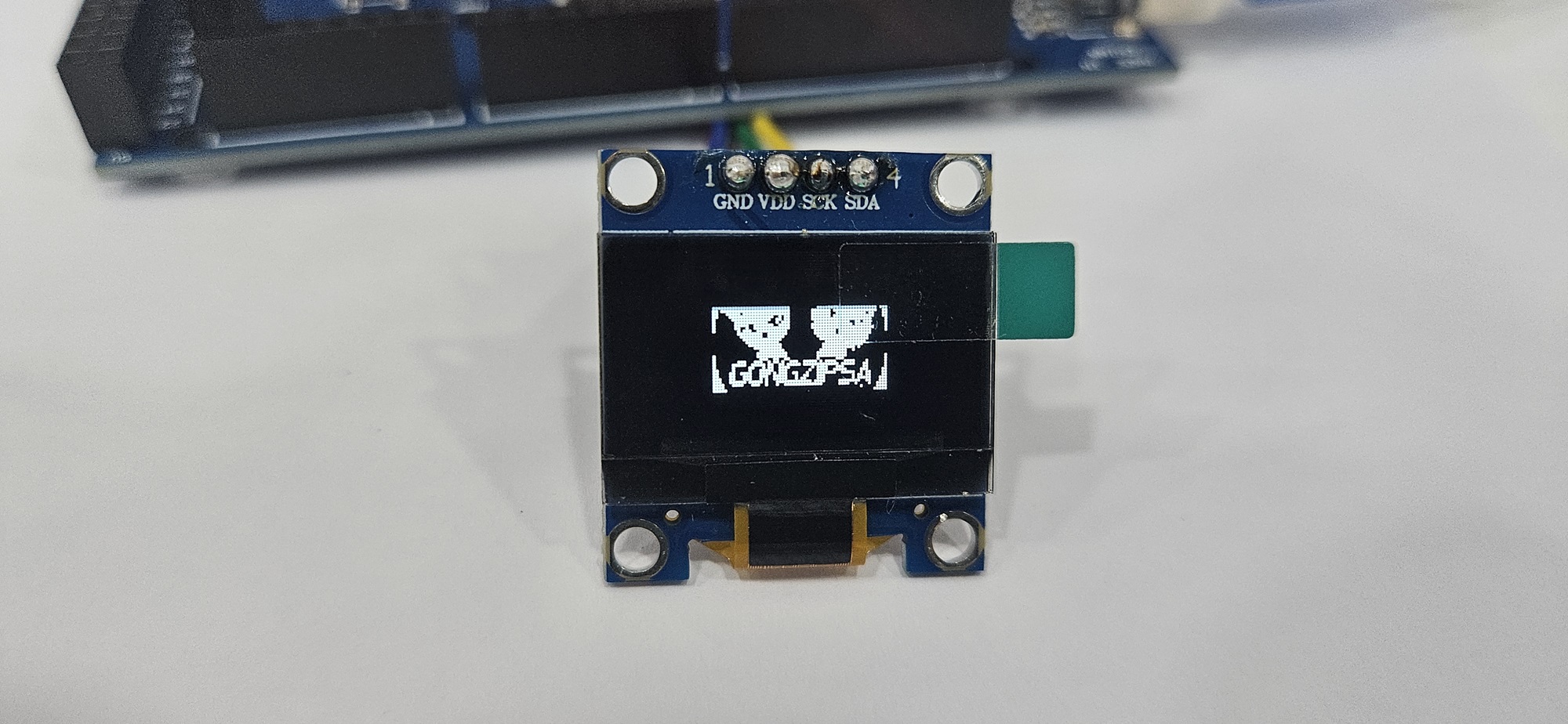
I used a 0.91-inch OLED, and since this module has a resolution of 128 x 32 pixels, I changed the 6th line SCREEN_HEIGHT from 64 to 32.
#include <Wire.h>
#include <Adafruit_GFX.h>
#include <Adafruit_SSD1306.h>

#define SCREEN_WIDTH 128  // OLED width
#define SCREEN_HEIGHT 32   // OLED height

// I2C address of the OLED module (typically 0x3D or 0x3C)
#define OLED_ADDR 0x3C

// Create Adafruit_SSD1306 object
Adafruit_SSD1306 display(SCREEN_WIDTH, SCREEN_HEIGHT, &Wire, -1);

void setup() {
  // OLED Initialization
  display.begin(SSD1306_SWITCHCAPVCC, OLED_ADDR);
  display.clearDisplay(); // Clear the screen
  display.setTextSize(1); // Set text size
  display.setTextColor(SSD1306_WHITE); // Set text color
  display.setCursor(0, 0); // Set cursor position
  display.println("GONGZIPSA"); // Print text
  display.setCursor(0, 10); // Set cursor position
  display.println("ArduWiki"); // Print text
  display.display(); // Display on the screen
}

void loop() {
}
The roles of the used functions are as follows.
| Functions | Explanation |
|---|---|
begin()
|
Initializes the OLED display. Sets the I2C address and resolution. |
clearDisplay()
|
Clears the current content of the display. Initializes the screen. |
setTextSize(size)
|
Sets the size of the text to be displayed. The size indicates the scale. (e.g., 1, 2, etc.)
|
setTextColor(color)
|
Sets the color of the text. Typically, SSD1306_WHITE and SSD1306_BLACK are used.
|
setCursor(x, y)
|
Sets the position where the text will be displayed. x is the horizontal position, and y is the vertical position.
(0, 0) is the top-left corner, and as |
| println("Contents") | Sets the content to be displayed. |
display()
|
Outputs the content stored in the buffer to the OLED display. |
Execution Result
3. Simple Shape Output
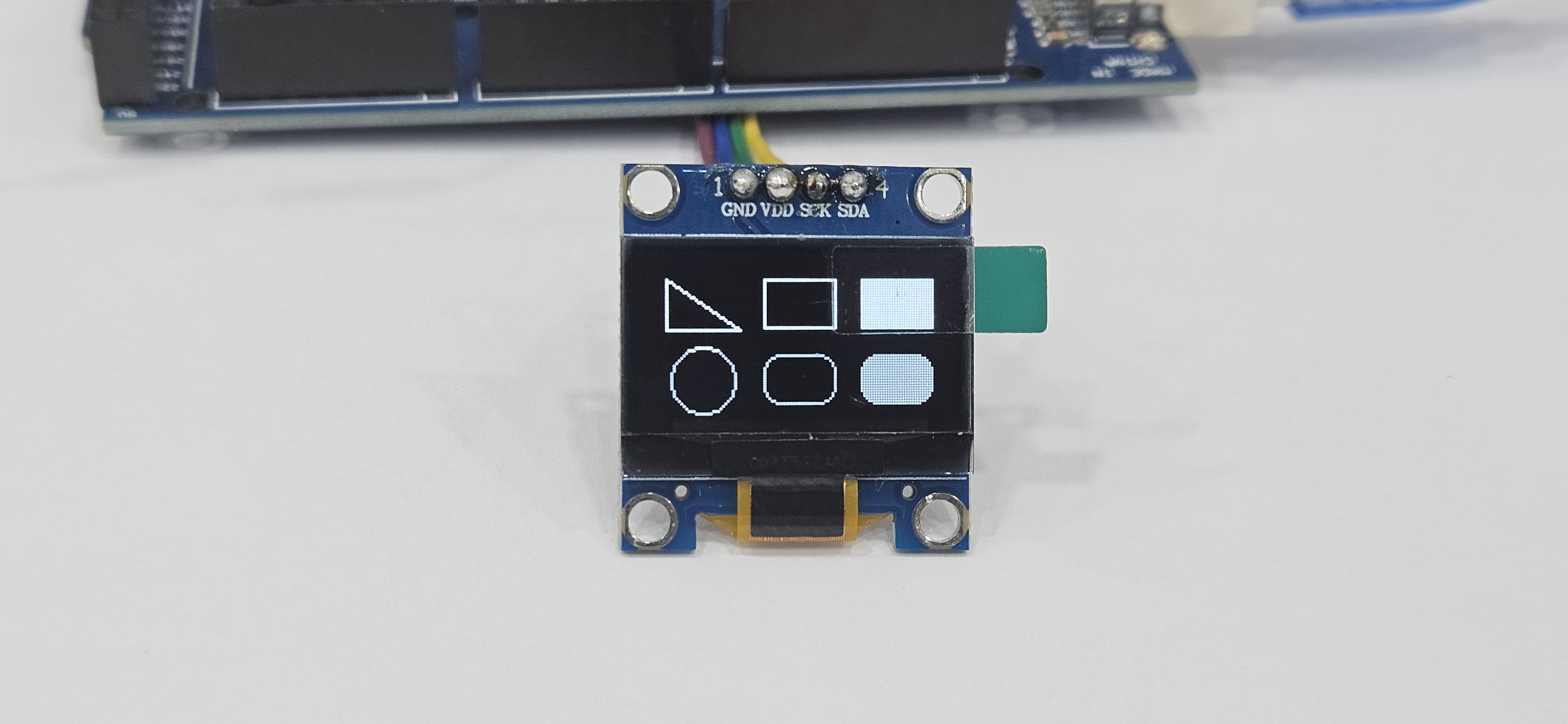
This is an example of outputting simple shapes such as rectangles, triangles, and circles.
#include <Wire.h>
#include <Adafruit_GFX.h>
#include <Adafruit_SSD1306.h>

#define SCREEN_WIDTH 128
#define SCREEN_HEIGHT 64
#define OLED_ADDR 0x3C

Adafruit_SSD1306 display(SCREEN_WIDTH, SCREEN_HEIGHT, &Wire, -1);

void setup() {
  display.begin(SSD1306_SWITCHCAPVCC, OLED_ADDR);
  display.clearDisplay(); // Clear the screen
  display.drawTriangle(10, 10, 40, 30, 10, 30, WHITE); // Draw a small triangle
  display.drawRect(50, 10, 30, 20, WHITE); // Draw a rectangle
  display.fillRect(90, 10, 30, 20, WHITE); // Draw a filled rectangle
  display.drawCircle(25, 50, 13, WHITE); // Draw a circle
  display.drawRoundRect(50, 40, 30, 20, 7, WHITE); // Draw a rounded rectangle
  display.fillRoundRect(90, 40, 30, 20, 7, WHITE); // Draw a filled rounded rectangle
  display.display(); // Display the shapes
}

void loop() {

}
The functions related to shapes are as follows:
| Functions | Explanation |
|---|---|
drawLine(x1, y1, x2, y2, color)
|
Draws a line connecting two points. |
drawRect(x, y, width, height, color)
|
Draws an empty rectangle. |
fillRect(x, y, width, height, color)
|
Draws a filled rectangle. |
drawCircle(x, y, radius, color)
|
Draws an empty circle. |
fillCircle(x, y, radius, color)
|
Draws a filled circle. |
drawTriangle(x1, y1, x2, y2, x3, y3, color)
|
Draws a triangle |
drawRoundRect(x, y, width, height, radius, color)
|
Draws an empty rectangle with rounded corners. |
fillRoundRect(x, y, width, height, radius, color)
|
Draws a filled rectangle with rounded corners. |
Execution Result
4. ASCII Code Output
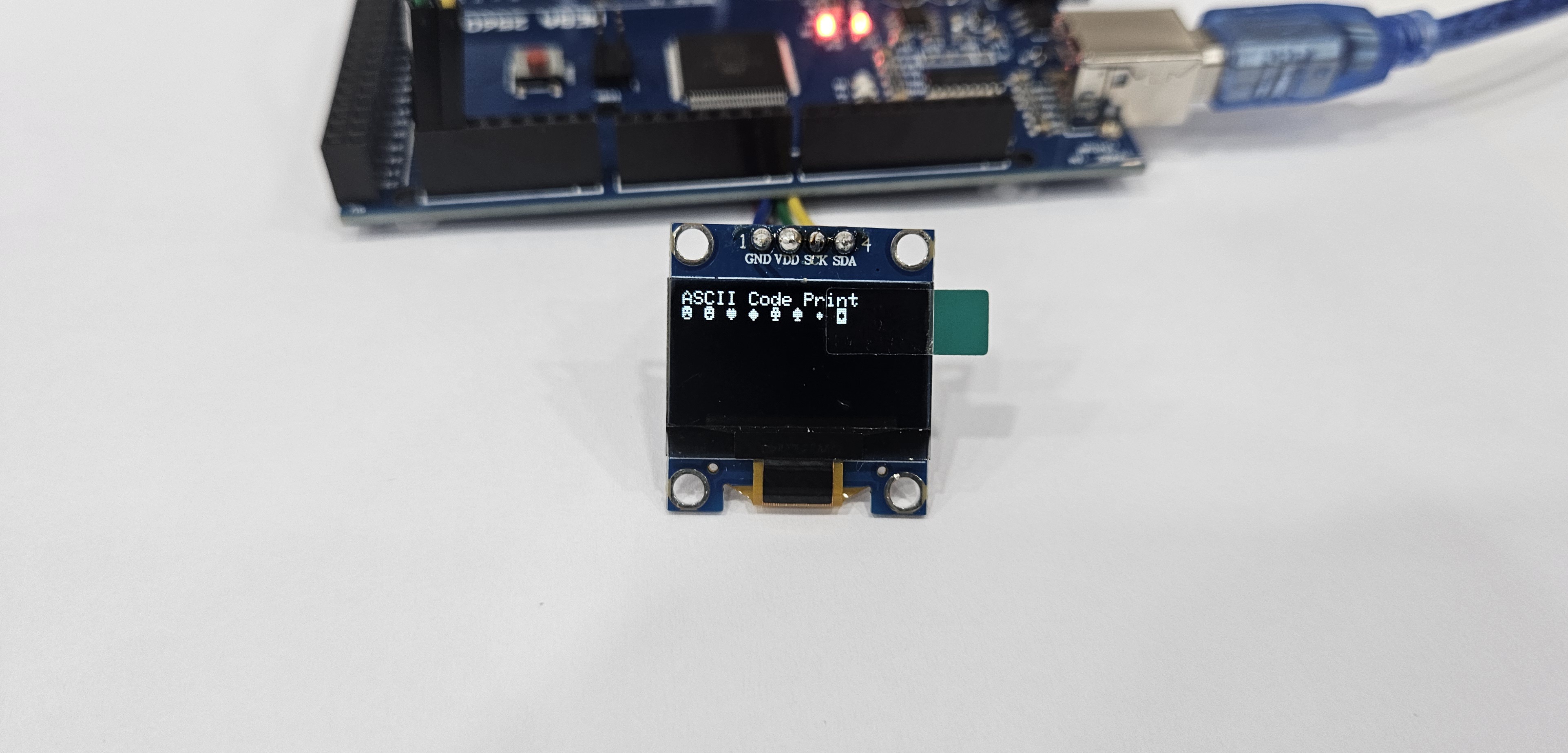
This is an example of outputting characters corresponding to ASCII codes 1 to 8.
For more characters, please refer to the ASCII code table.
#include <Wire.h>
#include <Adafruit_GFX.h>
#include <Adafruit_SSD1306.h>

#define SCREEN_WIDTH 128
#define SCREEN_HEIGHT 64
#define OLED_ADDR 0x3C

Adafruit_SSD1306 display(SCREEN_WIDTH, SCREEN_HEIGHT, &Wire, -1);

void setup() {
  display.begin(SSD1306_SWITCHCAPVCC, OLED_ADDR);
  display.clearDisplay(); // Clear the screen

  // Text output settings
  display.setTextSize(1);       // Set text size
  display.setTextColor(WHITE);  // Set text color
  display.setCursor(0, 0);      // Set cursor position

  // Print ASCII code characters
  display.println("ASCII Code Print");

  // Print ASCII code characters
  for (char c = 1; c < 9; c++) { // From ASCII code 1 to 8
      display.print(c);                // Print each character
      display.print(" ");              // Add space
  }

  display.display(); // Display the buffer content on the screen
}

void loop() {
}
Execution Result
5. Bitmap Image Output
This is an example of outputting an image on the OLED by converting it into a byte array.
How to Convert an Image to a Byte Array
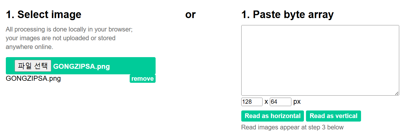
1. Go to image2cpp (javl.github.io).
2. Upload Image
Select a file to upload from the left-side Select image.
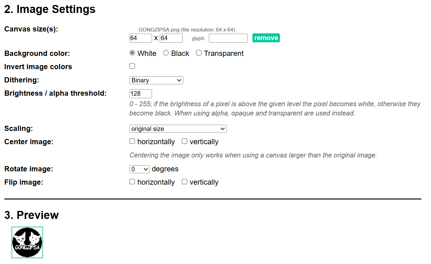
3. Image Settings
Enter the image size in the Canvas size field and check the Preview. If the image is too large and the Canvas size is not properly adjusted, the image may not display correctly in the Preview.
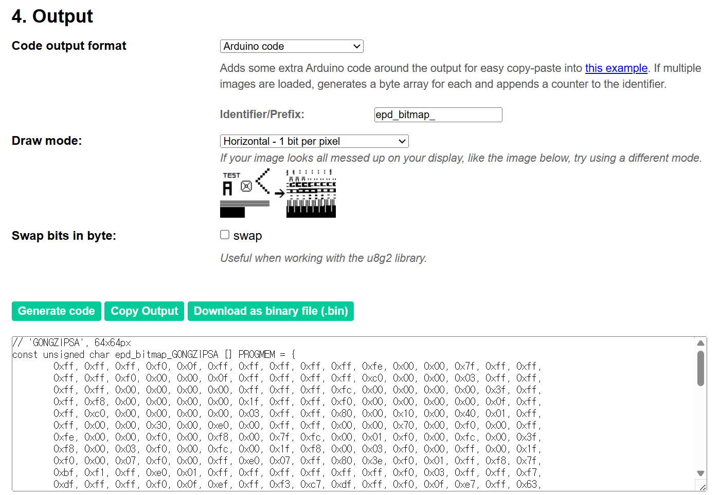
4. Output
Set the Code output format to Arduino Code and click Generate code. The array will be displayed below.
Copy the output array and use it in the example code.
Code
You can use the drawBitmap(x, y, bitmap, width, height, color) function to draw a bitmap image at a specified position.
The color is set to white, so the image will be displayed in white.
Change the const unsigned char ~ part on line 12 to the byte array you created above.
If the example image (64 x 64 size) is different in size, you will need to adjust the x and y cursor positions, as well as the width and height values in the drawBitmap function on line 56 to match the image size.
#include <Wire.h>
#include <Adafruit_GFX.h>
#include <Adafruit_SSD1306.h>

#define SCREEN_WIDTH 128
#define SCREEN_HEIGHT 64
#define OLED_ADDR 0x3C

Adafruit_SSD1306 display(SCREEN_WIDTH, SCREEN_HEIGHT, &Wire, -1);

// GONGZIPSA LOGO
const unsigned char GONGZIPSA [] PROGMEM = {
	0xff, 0xff, 0xff, 0xf0, 0x0f, 0xff, 0xff, 0xff, 0xff, 0xff, 0xfe, 0x00, 0x00, 0x7f, 0xff, 0xff,
	0xff, 0xff, 0xf0, 0x00, 0x00, 0x0f, 0xff, 0xff, 0xff, 0xff, 0xc0, 0x00, 0x00, 0x03, 0xff, 0xff,
	0xff, 0xff, 0x00, 0x00, 0x00, 0x00, 0xff, 0xff, 0xff, 0xfc, 0x00, 0x00, 0x00, 0x00, 0x3f, 0xff,
	0xff, 0xf8, 0x00, 0x00, 0x00, 0x00, 0x1f, 0xff, 0xff, 0xf0, 0x00, 0x00, 0x00, 0x00, 0x0f, 0xff,
	0xff, 0xc0, 0x00, 0x00, 0x00, 0x00, 0x03, 0xff, 0xff, 0x80, 0x00, 0x10, 0x00, 0x40, 0x01, 0xff,
	0xff, 0x00, 0x00, 0x30, 0x00, 0xe0, 0x00, 0xff, 0xff, 0x00, 0x00, 0x70, 0x00, 0xf0, 0x00, 0xff,
	0xfe, 0x00, 0x00, 0xf0, 0x00, 0xf8, 0x00, 0x7f, 0xfc, 0x00, 0x01, 0xf0, 0x00, 0xfc, 0x00, 0x3f,
	0xf8, 0x00, 0x03, 0xf0, 0x00, 0xfc, 0x00, 0x1f, 0xf8, 0x00, 0x03, 0xf0, 0x00, 0xff, 0x00, 0x1f,
	0xf0, 0x00, 0x07, 0xf0, 0x00, 0xff, 0xe0, 0x07, 0xff, 0x80, 0x3e, 0xf0, 0x01, 0xff, 0xf8, 0x7f,
	0xbf, 0xf1, 0xff, 0xe0, 0x01, 0xff, 0xff, 0xff, 0xff, 0xff, 0xff, 0xf0, 0x03, 0xff, 0xff, 0xf7,
	0xdf, 0xff, 0xff, 0xf0, 0x0f, 0xef, 0xff, 0xf3, 0xc7, 0xdf, 0xff, 0xf0, 0x0f, 0xe7, 0xff, 0x63,
	0xc3, 0xff, 0xfc, 0xb0, 0x0f, 0xef, 0xff, 0xe3, 0x81, 0xff, 0xf9, 0xb0, 0x0f, 0xff, 0xff, 0xc1,
	0x80, 0xff, 0xf1, 0x70, 0x07, 0xff, 0xcd, 0xc1, 0x80, 0xf9, 0xfc, 0xf0, 0x0f, 0xff, 0xef, 0xc1,
	0x80, 0xc9, 0xff, 0xf0, 0x0f, 0xff, 0xff, 0xe1, 0x80, 0x5c, 0xff, 0xe0, 0x07, 0xfb, 0xff, 0xc1,
	0x00, 0x7f, 0xcf, 0xe0, 0x07, 0xfb, 0xff, 0xc0, 0x00, 0x3f, 0xcf, 0xc0, 0x03, 0xff, 0xff, 0x80,
	0x00, 0x1f, 0xff, 0x80, 0x01, 0xff, 0xff, 0x80, 0x00, 0x0f, 0xff, 0x00, 0x00, 0x7f, 0xff, 0x00,
	0x00, 0x07, 0xff, 0x80, 0x00, 0xff, 0xfe, 0x00, 0x00, 0x01, 0xff, 0x80, 0x00, 0xff, 0xf4, 0x00,
	0x00, 0x00, 0x7f, 0xc0, 0x01, 0xff, 0x90, 0x00, 0x00, 0x00, 0xff, 0xe0, 0x03, 0xff, 0x80, 0x00,
	0x80, 0x00, 0xff, 0xe0, 0x03, 0xff, 0x80, 0x01, 0x80, 0x00, 0x73, 0x30, 0x02, 0x07, 0x00, 0x01,
	0x80, 0x71, 0xcb, 0x4e, 0x7d, 0x78, 0xf0, 0x81, 0x81, 0xf3, 0xec, 0xdf, 0x7f, 0xfd, 0xf1, 0x81,
	0x81, 0x06, 0x2c, 0xf0, 0x0b, 0xc7, 0x01, 0x81, 0xc1, 0x04, 0x7c, 0xe0, 0x13, 0xcf, 0x83, 0x83,
	0xc3, 0x3c, 0x7a, 0xe6, 0x23, 0xf9, 0xf2, 0xc3, 0xc3, 0x1c, 0x73, 0xe2, 0x63, 0x80, 0x16, 0xc3,
	0xe3, 0x1c, 0x53, 0xe2, 0xc3, 0x80, 0x17, 0xc7, 0xe3, 0xf7, 0xd1, 0xff, 0xf7, 0x83, 0xfc, 0xc7,
	0xf1, 0xe3, 0x91, 0x3f, 0xff, 0x03, 0xc8, 0x4f, 0xf0, 0x00, 0x00, 0x00, 0x00, 0x00, 0x02, 0x0f,
	0xf8, 0x00, 0x00, 0x00, 0x00, 0x00, 0x00, 0x1f, 0xf8, 0x00, 0x00, 0x00, 0x00, 0x00, 0x00, 0x1f,
	0xfc, 0x00, 0x00, 0x00, 0x00, 0x00, 0x00, 0x3f, 0xfe, 0x00, 0x00, 0x00, 0x00, 0x00, 0x00, 0x7f,
	0xff, 0x00, 0x00, 0x00, 0x00, 0x00, 0x00, 0xff, 0xff, 0x00, 0x00, 0x00, 0x00, 0x00, 0x00, 0xff,
	0xff, 0x80, 0x00, 0x00, 0x00, 0x00, 0x01, 0xff, 0xff, 0xc0, 0x00, 0x00, 0x00, 0x00, 0x03, 0xff,
	0xff, 0xf0, 0x00, 0x00, 0x00, 0x00, 0x0f, 0xff, 0xff, 0xf8, 0x00, 0x00, 0x00, 0x00, 0x1f, 0xff,
	0xff, 0xfc, 0x00, 0x00, 0x00, 0x00, 0x3f, 0xff, 0xff, 0xff, 0x00, 0x00, 0x00, 0x00, 0xff, 0xff,
	0xff, 0xff, 0xc0, 0x00, 0x00, 0x03, 0xff, 0xff, 0xff, 0xff, 0xf0, 0x00, 0x00, 0x0f, 0xff, 0xff,
	0xff, 0xff, 0xfe, 0x00, 0x00, 0x7f, 0xff, 0xff, 0xff, 0xff, 0xff, 0xf0, 0x0f, 0xff, 0xff, 0xff
};

void setup() {
  display.begin(SSD1306_SWITCHCAPVCC, OLED_ADDR);
  display.clearDisplay(); // Screen initialization
}

void loop() {
  display.clearDisplay(); // Clear the screen

  // Drawing a 64x64 bitmap image
  display.drawBitmap(32, 0, GONGZIPSA, 64, 64, WHITE); // (x, y, bitmap, width, height, color)

  display.display(); // Output the buffer contents to the screen
}
Execution Result
Due to flickering, the image appears cut off when captured, but in reality, the round logo is displayed clearly.
