Relay Module En: 두 판 사이의 차이
잔글편집 요약 없음 |
잔글 (→2-1. Connections) |
||
| 121번째 줄: | 121번째 줄: | ||
| colspan="1" rowspan="1" |2ch Relay Module | | colspan="1" rowspan="1" |2ch Relay Module | ||
| colspan="1" rowspan="1" |Resistor1 | | colspan="1" rowspan="1" |Resistor1 | ||
| colspan="1" rowspan="1" | | | colspan="1" rowspan="1" |Resistor2 | ||
| colspan="1" rowspan="1" |LED1 | | colspan="1" rowspan="1" |LED1 | ||
| colspan="1" rowspan="1" |LED2 | | colspan="1" rowspan="1" |LED2 | ||
2024년 8월 9일 (금) 17:30 판

The Arduino relay module is an electronic switch that allows control of high-voltage devices through microcontrollers like Arduino.
It can open and close high-voltage circuits using low-voltage signals, making it useful for controlling household electrical appliances and industrial equipment.
Components
Relay Module : The relay module consists of one or more relays and the electronic circuits required to control them.
Control Pin : This is the pin that receives the signal from Arduino to control the relay.
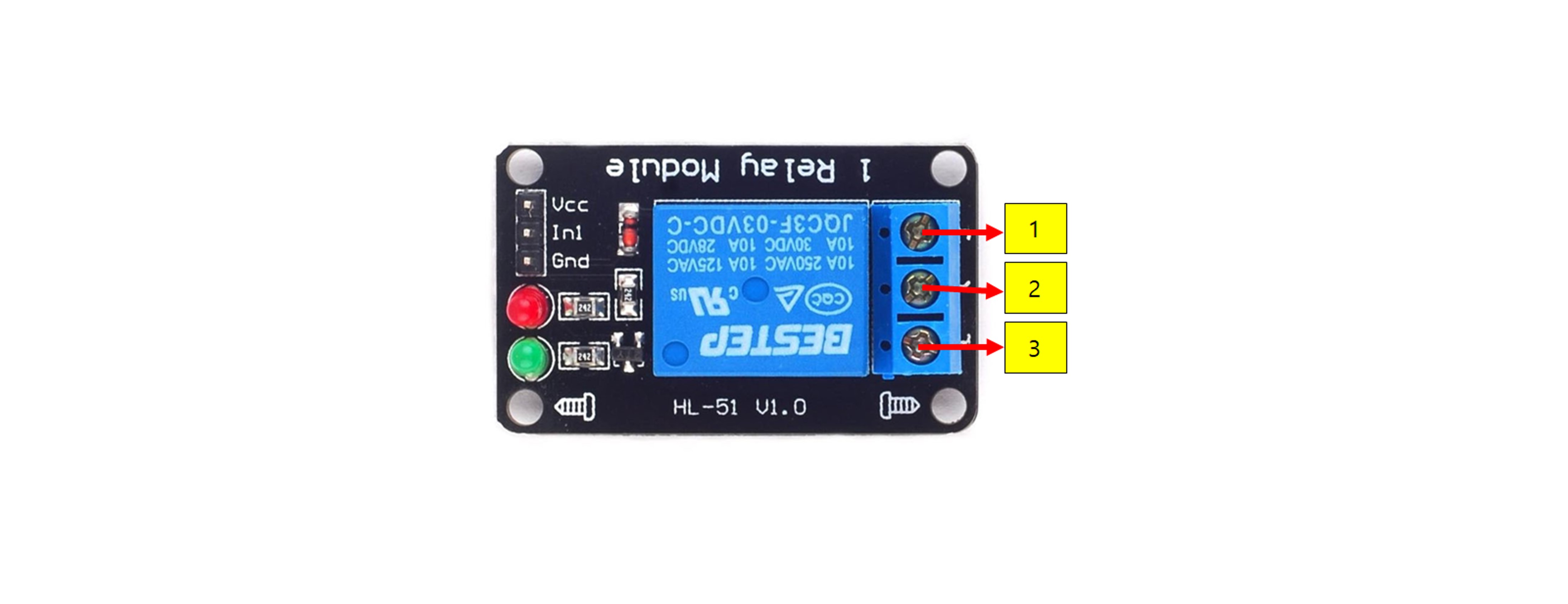
Contacts : This part performs the electrical switching, typically categorized as NO (Normally Open), NC (Normally Closed), and COM (Common).

Relay Operating Principle
It operates based on electromagnetic principles. Inside, there is a coil, and when current flows through it via the control pin, the coil generates a magnetic field that activates the internal switch.
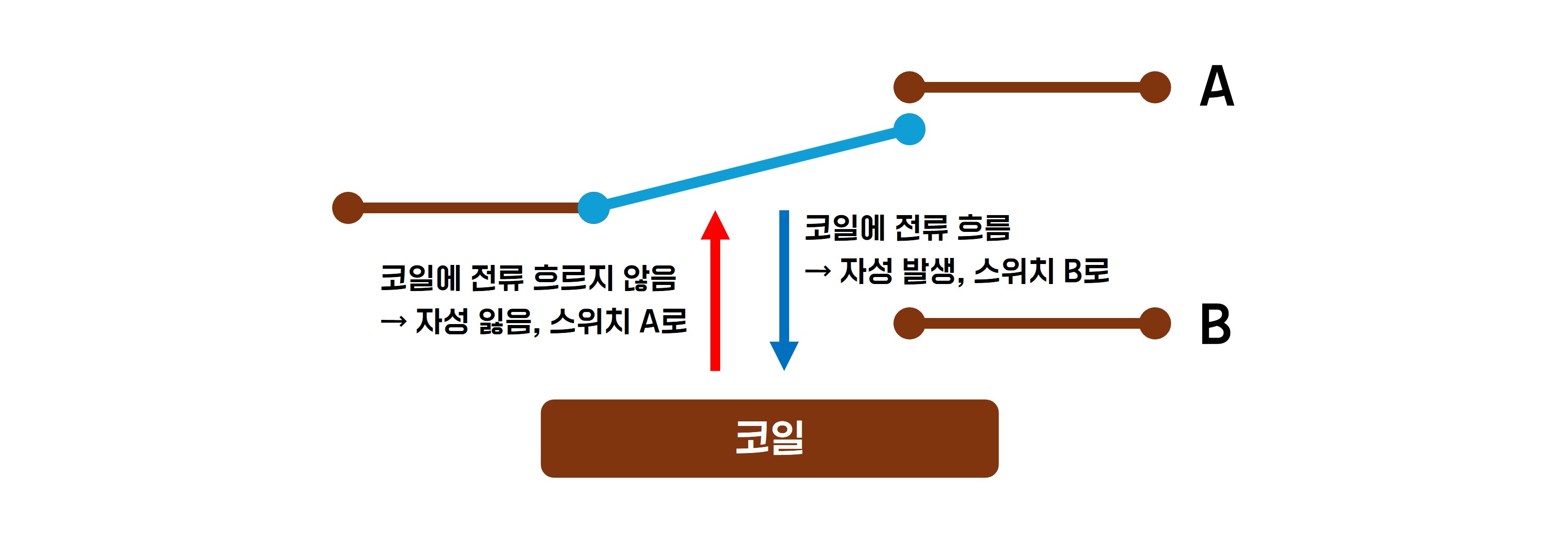
Low Level Trigger : When a low voltage (typically 0V or GND) is applied to the control pin, the relay is activated.
High Level Trigger : When a high voltage (typically 5V) is applied to the control pin, the relay is activated.
Example Hardware Used
- Arduino
- Relay Module
- Jumper Cable
- Resistor
- LED
Usage Example
1. 1 Channel Relay
This is an example of changing the state of a single-channel relay three times. The changes can be confirmed through an LED.
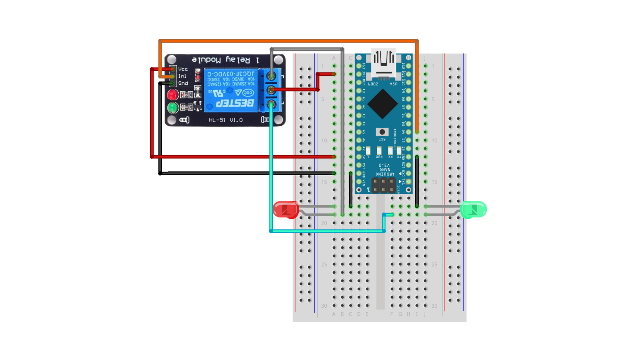
1-1. Connections
| Arduino Nano | Relay | LED Red | LED Green |
| 5V | VCC | ||
| 3.3V | 2 | ||
| GND | GND | - | - |
| D4 | In1 | ||
| 1 | + | ||
| 3 | + |
1-2. Code
const int relay = 4;

void setup() {
  pinMode(relay, OUTPUT);
  digitalWrite(relay, HIGH);
}

void loop() {
  for (int i = 0; i < 3; i++) {
    digitalWrite(relay, LOW);
    delay(500);
    digitalWrite(relay, HIGH);
    delay(500);
  }
  delay(9999);
}
1-3. Execution Result
2. Dual Channel Relay
This example controls each LED connected to the two channels so that they turn on in sequence and then turn off again.
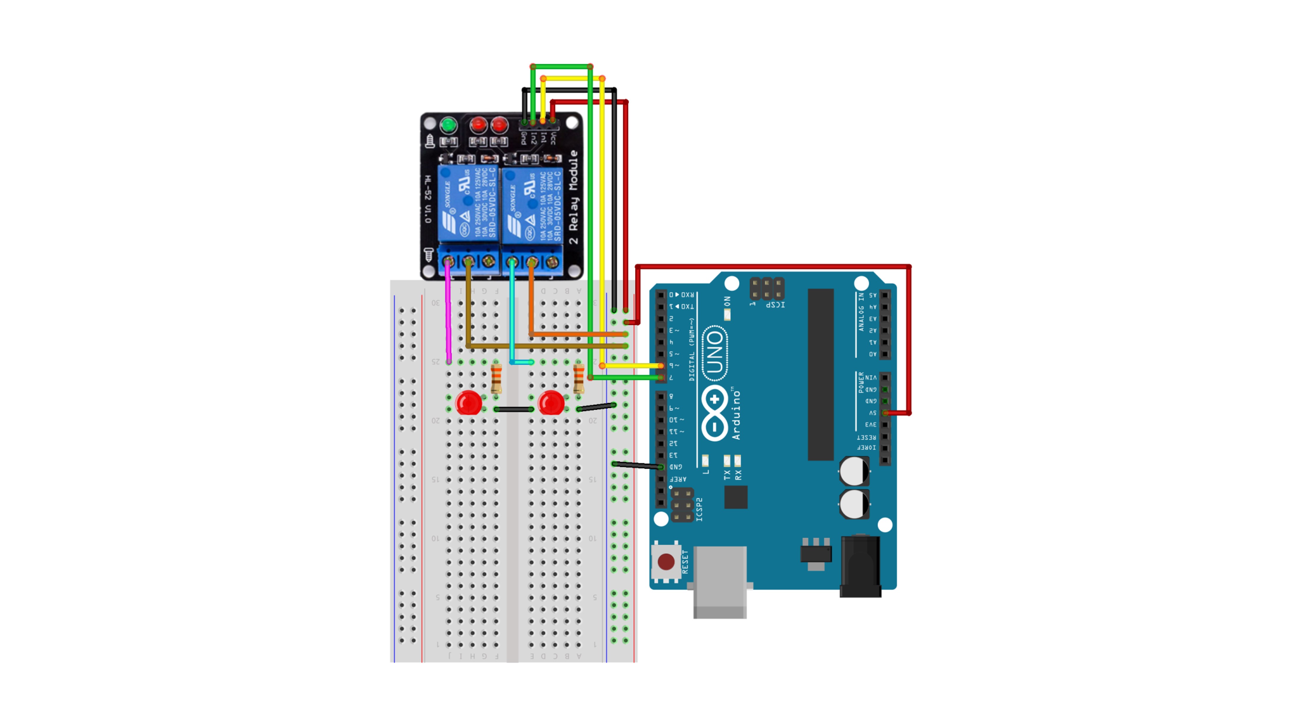
2-1. Connections
| Arduino Uno | 2ch Relay Module | Resistor1 | Resistor2 | LED1 | LED2 |
| GND | Gnd | K | K | ||
| 5V | Vcc, 2, 4 | ||||
| D6 | IN1 | ||||
| D7 | IN2 | ||||
| 1 | Connect | ||||
| 3 | Connect | ||||
| Connect | A | ||||
| Connect | A |

2-2. Code
#define IN1 6
#define IN2 7

void setup() {
  pinMode(IN1, OUTPUT);
  pinMode(IN2, OUTPUT);
  digitalWrite(IN1, HIGH);
  digitalWrite(IN2, HIGH);
  delay(300);
  digitalWrite(IN1, LOW);
  delay(300);
  digitalWrite(IN2, LOW);
  delay(300);
  digitalWrite(IN1, HIGH);
  delay(300);
  digitalWrite(IN2, HIGH);
  delay(300);
}

void loop() {
}
2-3. Execution Result
3. 4-Channel Relay
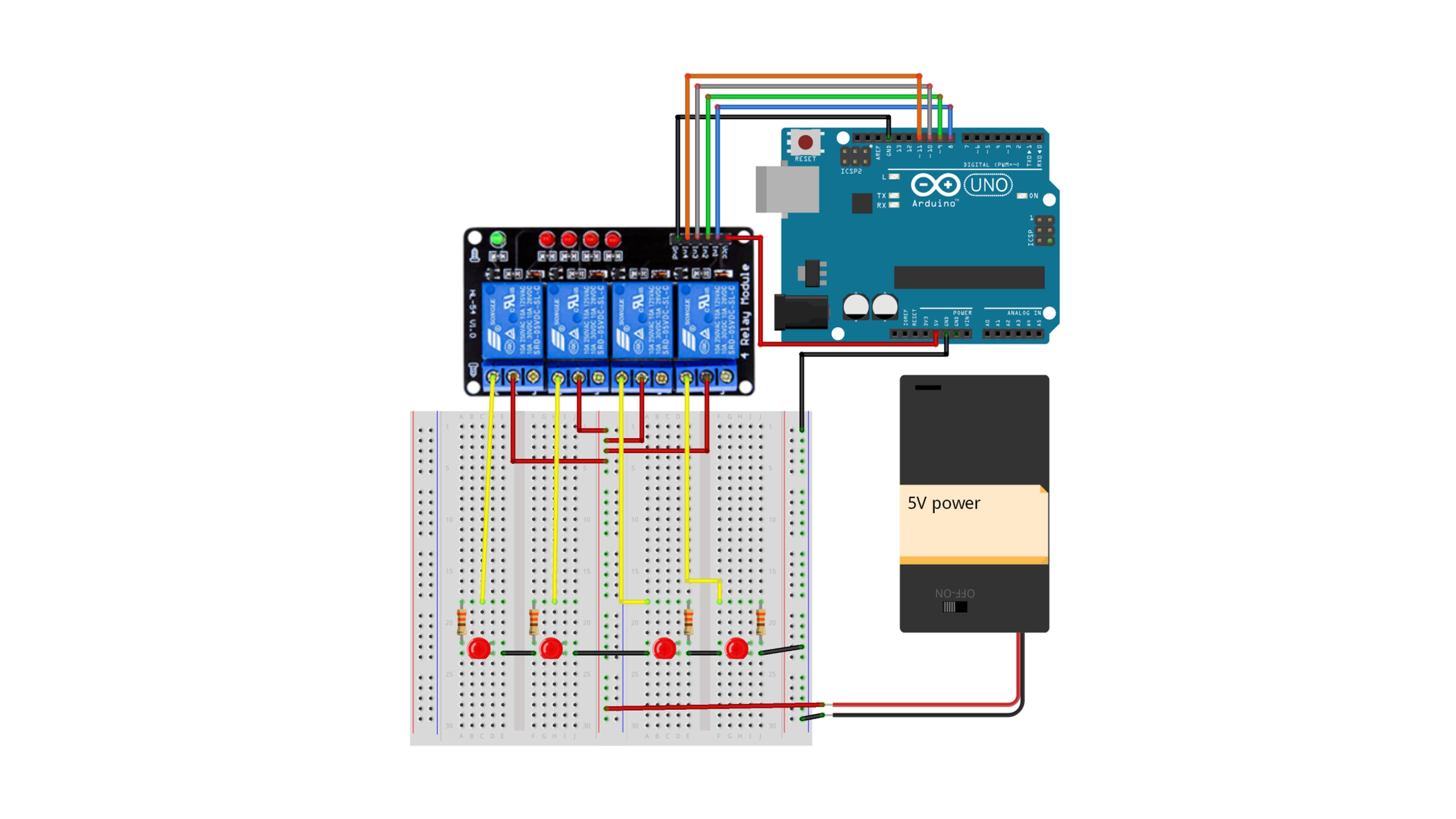
This is an example of controlling each LED connected to the four channels to turn on in sequence and then turn off.
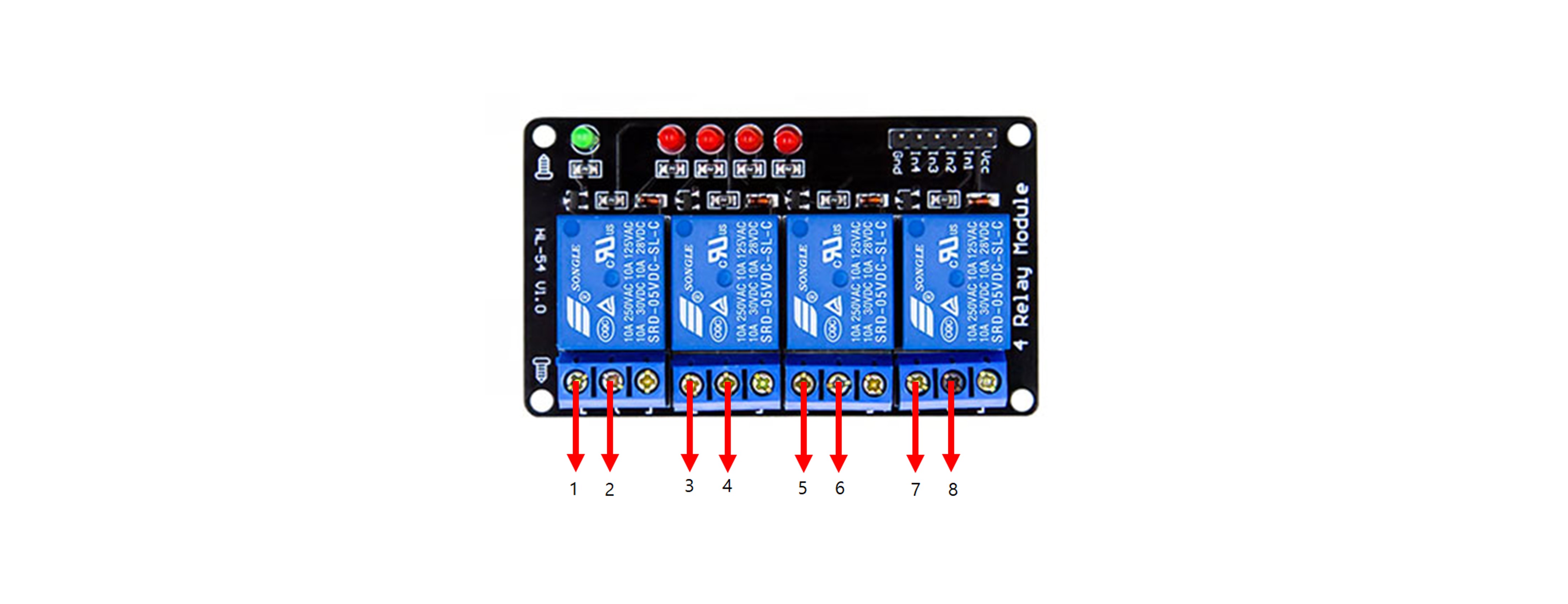
3-1. Connections
| Arduino | 4ch relay module | LED1 | LED2 | LED3 | LED4 | Resistor1 | Resistor2 | Resistor3 | Resistor4 | 5V |
| 5V | VCC | |||||||||
| GND | GND | K | K | K | K | - | ||||
| D8 | IN1 | |||||||||
| D9 | IN2 | |||||||||
| D10 | IN3 | |||||||||
| D11 | IN4 | |||||||||
| 1 | Connect | |||||||||
| 3 | Connect | |||||||||
| 5 | Connect | |||||||||
| 7 | Connect | |||||||||
| 2,4,6,8 | + | |||||||||
| A | Connect | |||||||||
| A | Connect | |||||||||
| A | Connect | |||||||||
| A | Connect |
3-2. Code
#define IN1 8
#define IN2 9
#define IN3 10
#define IN4 11

void setup() {
  for (int i = 0; i < 4; i++) {
    pinMode(IN1 + i, OUTPUT);
    digitalWrite(IN1 + i, HIGH);
  }
  delay(100);
  for (int i = 0; i < 4; i++) {
    digitalWrite(IN1 + i, LOW);
    delay(100);
  }
  delay(1000);
  for (int i = 0; i < 4; i++) {
    digitalWrite(IN1 + i, HIGH);
    delay(100);
  }
  delay(2000);
}

void loop() {
}
3-3. Execution Result
4. 8-Channel Relay
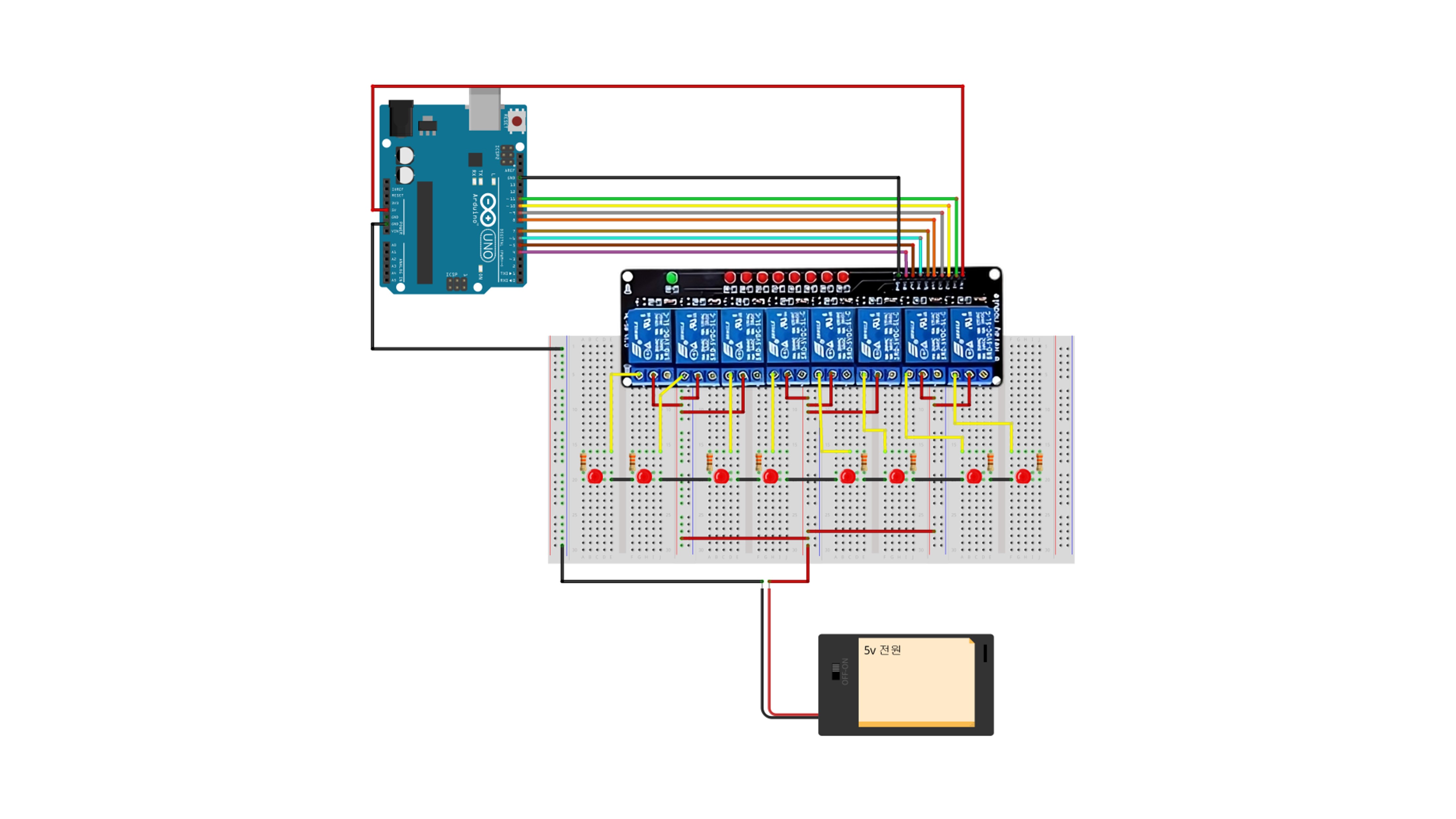
This is an example of controlling each LED connected to the eight channels to turn on in sequence and then turn off.
4-1. Connections
4-2. Code
const int IN8 = 4;
const int IN7 = 5;
const int IN6 = 6;
const int IN5 = 7;
const int IN4 = 8;
const int IN3 = 9;
const int IN2 = 10;
const int IN1 = 11;

void setup() {
  Serial.begin(9600);
  for (int i = 0; i < 8; i++) {
    pinMode(IN8 + i, OUTPUT);
    digitalWrite(IN8 + i, HIGH);
  }
  delay(100);
  for (int i = 0; i < 8; i++) {
    digitalWrite(IN1 - i, LOW);
    delay(100);
  }
  delay(1000);
  for (int i = 0; i < 8; i++) {
    digitalWrite(IN1 - i, HIGH);
    delay(100);
  }
}

void loop() {
}
4-3. Execution Result
Precautions
- The power supply to the relay module should be stable.
- Safety should be prioritized when handling high-voltage devices.
- Care should be taken not to exceed the maximum current and voltage ratings of the relay module.
Applications
1. Home Automation
- Lighting Control: Relays can be used to remotely turn on and off home lighting.
- Appliance Control: Various appliances like air conditioners, heaters, and coffee machines can be controlled.
2. Security Systems
- Door Lock Control: Relays can be used to control electronic door locks.
- Alarm Systems: A security system can be built by integrating sensors with relays.
3. Automated Control Systems
- Temperature Control: Temperature sensors and relays can be used to control fans or heaters.
- Water Pump Control: Water pumps can be automatically controlled in conjunction with level sensors.
4. Remote Control
- IoT (Internet of Things) Projects: Relays can be controlled remotely via the internet to manage various devices.
5. Traffic Signal Control
- Traffic Lights: Relays can be used to control traffic signal systems.
== Purchase Links