Joystick Module(KY-023): 두 판 사이의 차이
(Created page with "{{#seo:|title=아두위키 : 아두이노 조이스틱 모듈 가이드|title_mode=append|keywords=아두이노, 정보과학, 메이커학습, 수행평가, 조이스틱 모듈, 아두이노 작품, 캡스톤작품, 아두이노 예제코드|description=아두이노로 조이스틱 모듈을 제어하는 방법(기본정보, 회로, 예제 코드)을 소개합니다. 정보과학과 메이커수업에 활용가능합니다.}} File:조이스틱대표이미지.jpg|cente...") |
잔글편집 요약 없음 |
||
| 96번째 줄: | 96번째 줄: | ||
=== Execution Result === | === Execution Result === | ||
<div class="coders70"> | |||
<youtube> VnOB15SRHLE </youtube> | |||
</div> | |||
2024년 7월 10일 (수) 14:35 판

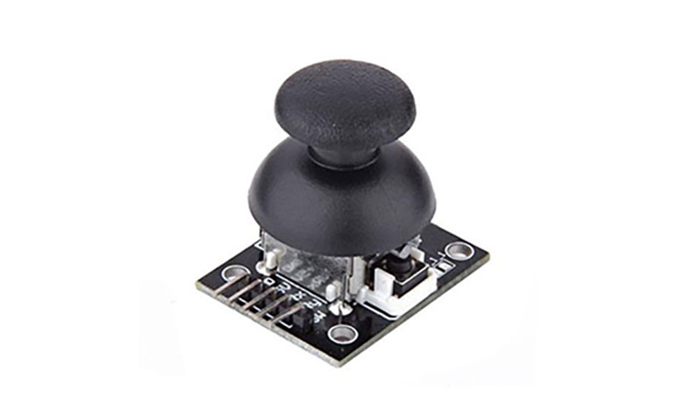
This module functions as a joystick, changing its x and y-axis values according to the resistance variations. Pressing the center button acts as a switch. It's commonly used in remote control cars, drones, and other applications requiring movement control.
Specifications
- Operating Voltage: 3.3V ~ 5V
- Analog output for x and y axes
- Digital output for the z-axis switch (without pull-up resistor)
Example Required Hardware
- Arduino board
- Jumper cables
- Joystick Module
- LCD 1602
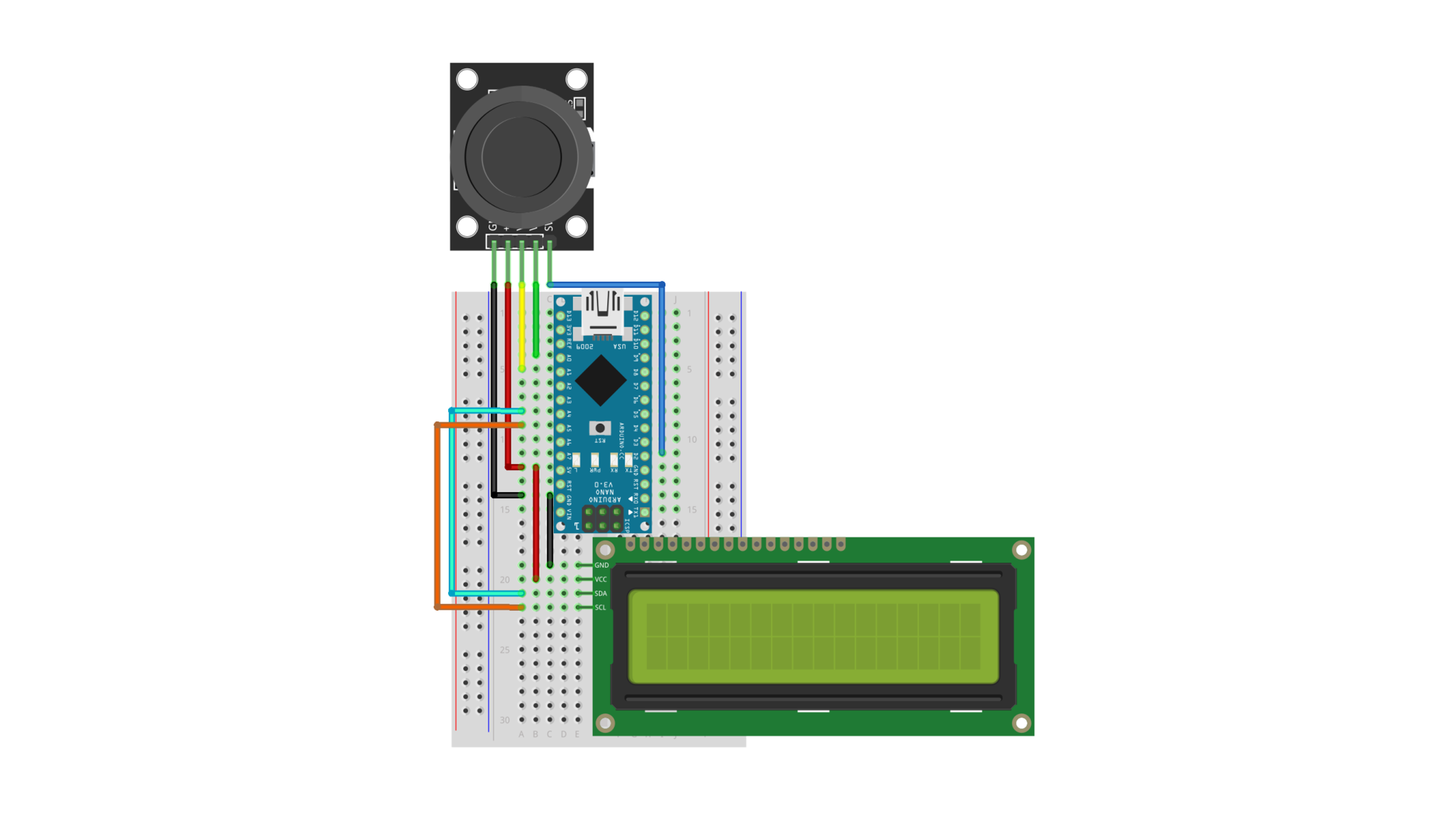
Connection
| Arduino | LCD | Joystick Module |
| 5V | VCC | 5V |
| GND | GND | GND |
| A1 | VRx | |
| A0 | VRy | |
| D2 | SW | |
| A4 | SDA | |
| A5 | SCL |

Example Code
This example displays the joystick's coordinates and switch state on an LCD screen.
Please refer to the link for instructions on using the LCD.
#include <Wire.h>
#include <LiquidCrystal_I2C.h>
LiquidCrystal_I2C lcd(0x27, 16, 2);

const int xAxis = A1;
const int yAxis = A0;
const int zSwitch = 2;

void setup() {
  pinMode(zSwitch, INPUT_PULLUP);
  lcd.init();
  lcd.backlight();
  lcd.setCursor(0, 0);
  lcd.print("X:");
  lcd.setCursor(8, 0);
  lcd.print("Y:");
  lcd.setCursor(0, 1);
  lcd.print("Z : ");
}

void loop() {
  for (int i = 2; i < 6; i++) {
    lcd.setCursor(i, 0);
    lcd.print(" ");
  }
  lcd.setCursor(2, 0);
  lcd.print(analogRead(xAxis));
  for (int i = 10; i < 14; i++) {
    lcd.setCursor(i, 0);
    lcd.print(" ");
  }
  lcd.setCursor(10, 0);
  lcd.print(analogRead(yAxis));
  lcd.setCursor(4, 1);
  lcd.print(digitalRead(zSwitch));
  delay(100);
}
Execution Result