RGB LED(5mm): 두 판 사이의 차이
(Created page with "{{#seo:|title=아두위키 : 아두이노 RGB LED 가이드|title_mode=append|keywords=아두이노, 정보과학, 메이커학습, 수행평가, 초음파 센서, 아두이노 작품, 캡스톤작품, 아두이노 예제코드|description=아두이노로 RGB LED를 제어하는 방법(기본정보, 회로, 예제 코드)를 소개합니다. 정보과학과 메이커수업에 활용가능합니다.}} center|class=coders100 This is a 4-pin RGB...") |
잔글 (→'실행 결과') |
||
| (같은 사용자의 중간 판 하나는 보이지 않습니다) | |||
| 105번째 줄: | 105번째 줄: | ||
</syntaxhighlight> | </syntaxhighlight> | ||
===실행 결과=== | |||
<div class="coders70"> | |||
<youtube> yR3n4U2cAfA </youtube> | |||
</div> | |||
2024년 7월 10일 (수) 14:13 기준 최신판

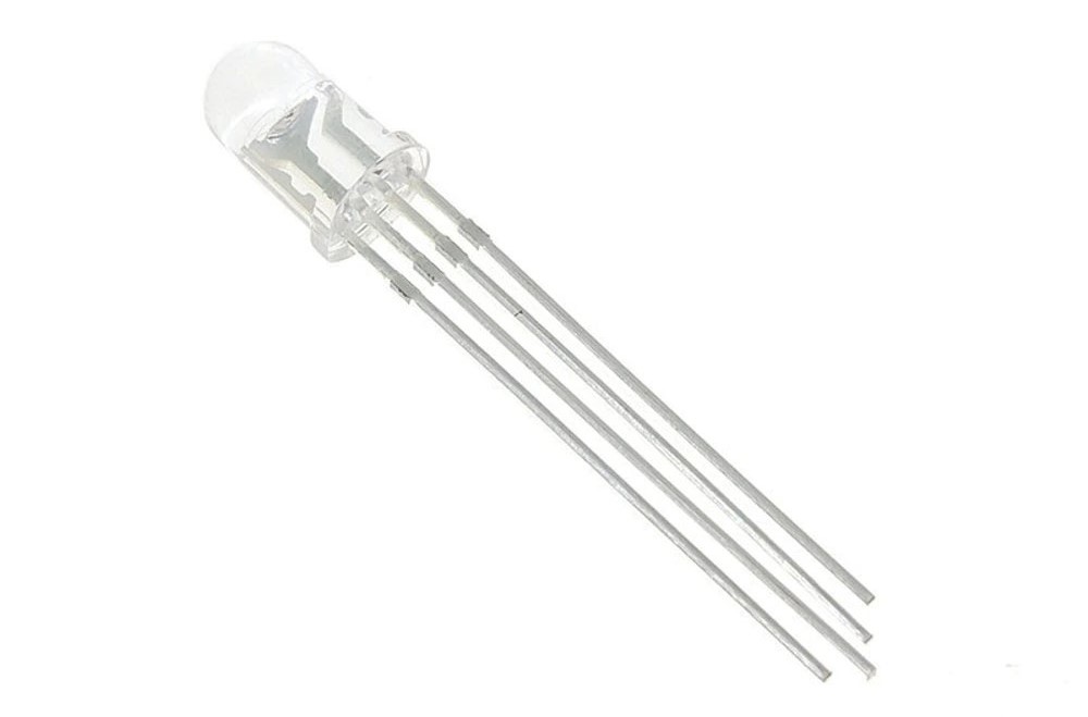
This is a 4-pin RGB LED that expresses colors by adjusting the RGB values.
There are Cathode and Anode versions of the product; this document uses the Cathode version.
Specifications
- Operating Voltage [V]: Red (22.2), Green (33.2), Blue (3~3.2)
- Common Cathode type
Example Hardware Used
- Arduino board
- Jumper cables
- RGB LED
- Three 330-ohm resistors (100-ohm, 220-ohm resistors, etc., can also be used.)
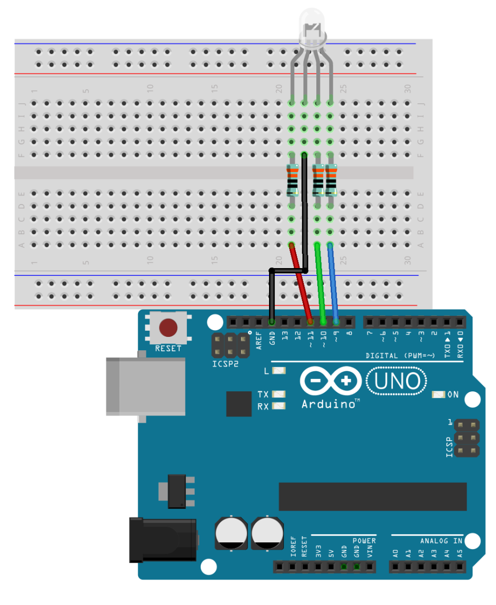
Connection
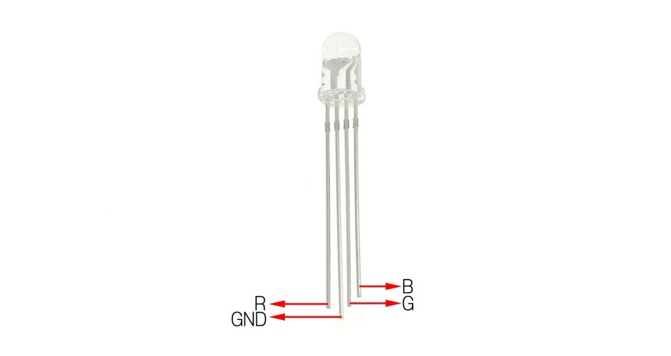
The long leg is GND, and excluding the long leg, from left to right, it is R, G, B as shown in the image below.

| Arduino | Resistor1 | Resistor2 | Resistor3 | RGB LED |
| GND | GND | |||
| D11 | Connected | |||
| D10 | Connected | |||
| D9 | Connected | |||
| Connected | R | |||
| Connected | G | |||
| Connected | B |

Example Code
This code sequentially lights up six different colors.
#define ledR 11
#define ledG 10
#define ledB 9

void brightness(int r, int g, int b) {
  analogWrite(ledR, r);
  analogWrite(ledG, g);
  analogWrite(ledB, b);
}

void setup() {
  brightness(0, 0, 0);
  delay(500);
  brightness(255, 0, 0);
  delay(500);
  brightness(0, 255, 0);
  delay(500);
  brightness(0, 0, 255);
  delay(500);
  brightness(255, 255, 0);
  delay(500);
  brightness(255, 0, 255);
  delay(500);
  brightness(0, 255, 255);
  delay(500);
  brightness(0, 0, 0);
}

void loop() {
}
실행 결과