3x4 Matrix Keypad: 두 판 사이의 차이
(Created page with "{{#seo:|title=아두위키 : 아두이노 3x4 키패드 가이드|title_mode=append|keywords=아두이노, 정보과학, 메이커학습, 수행평가, 3x4 키패드, 아두이노 작품, 캡스톤작품, 아두이노 예제코드|description=아두이노로 3x4 키패드를 제어하는 방법(기본정보, 회로, 예제 코드)을 소개합니다. 정보과학과 메이커수업에 활용가능합니다.}} [[File:3X4키패드대표이미지.jpg|center|class=coders100]...") |
잔글편집 요약 없음 |
||
| 65번째 줄: | 65번째 줄: | ||
}; | }; | ||
byte rowPins[ROWS] = { 5, 3 | byte rowPins[ROWS] = { 5, 4, 3, 2 }; | ||
byte colPins[COLS] = { 8, 7, 6 }; | byte colPins[COLS] = { 8, 7, 6 }; | ||
2024년 12월 6일 (금) 21:13 기준 최신판

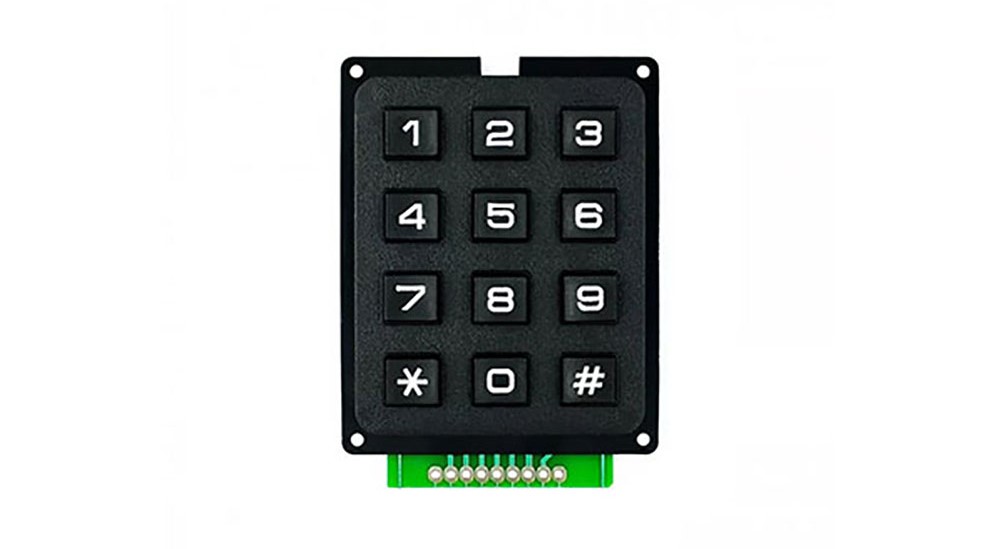
It's a 3x4 numeric type keypad. The far-left and far-right pins are not used, leaving pins 1 to 7, starting from the left, for use.
You can check the pin numbers in the image provided.
[For example, pressing '1' on the keypad will output signals from pins 3 and 2.]
Specifications
- Operating Voltage: 3 ~ 5V
- Resistance: 10 ~ 150 ohms
Example Required Hardware
- Arduino board
- Jumper cables
- 3x4 keypad
Library
- Keypad by Mark Stanley, Alexander Brevig (installable via the Library Manager)
- Please refer to the Arduino library link for instructions on how to use the library.
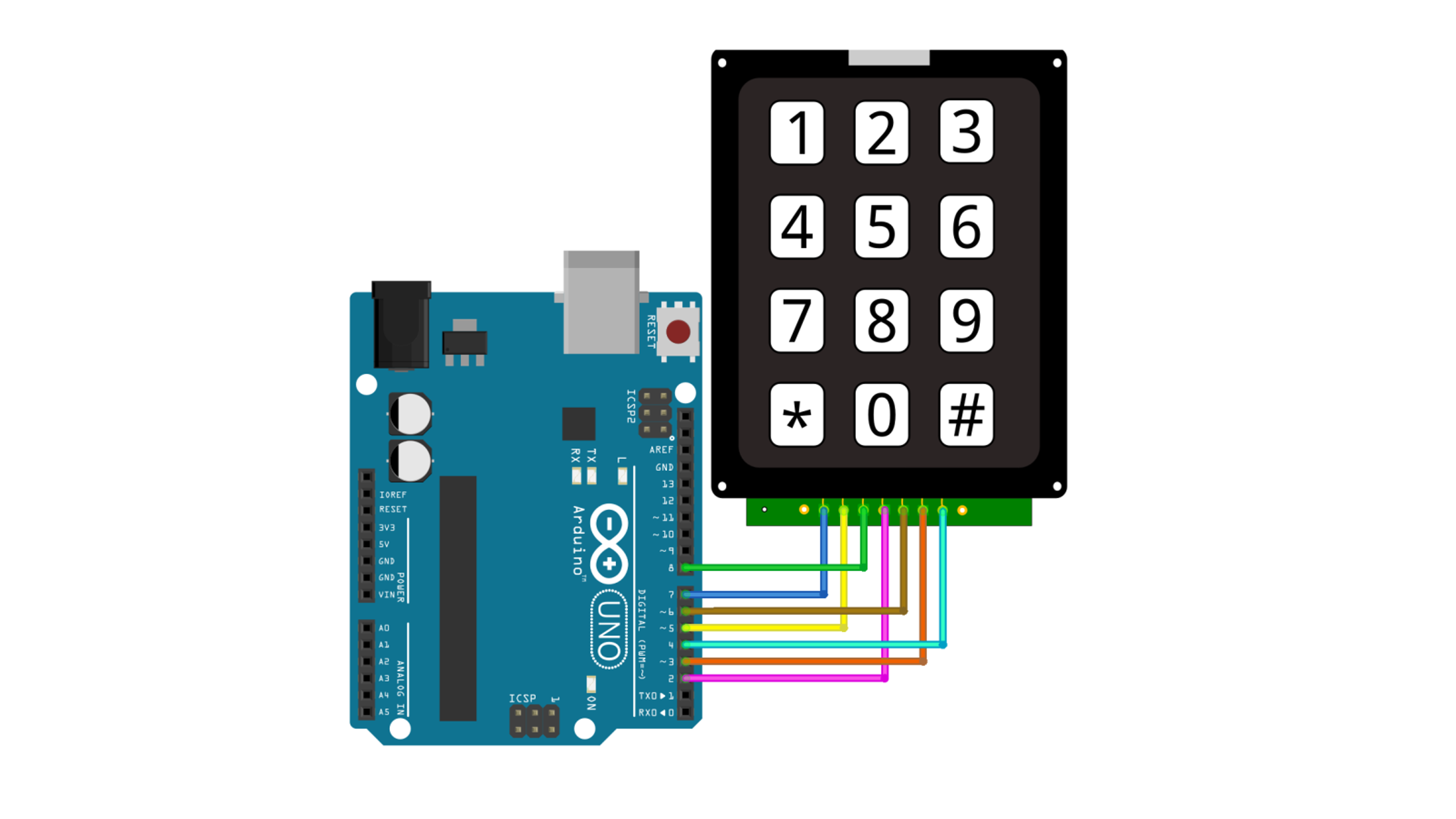
Connection
| keypad | Arduino | |||
| 1 | D7 | |||
| 2 | D5 | |||
| 3 | D8 | |||
| 4 | D2 | |||
| 5 | D6 | |||
| 6 | D3 | |||
| 7 | D4 | |||

example code
This code outputs to the serial monitor when a key on the keypad is pressed.
#include <Keypad.h>

const byte ROWS = 4;
const byte COLS = 3;

char keys[ROWS][COLS] = {
  { '1', '2', '3' },
  { '4', '5', '6' },
  { '7', '8', '9' },
  { '*', '0', '#' }
};

byte rowPins[ROWS] = { 5, 4, 3, 2 };
byte colPins[COLS] = { 8, 7, 6 };

Keypad keypad = Keypad(makeKeymap(keys), rowPins, colPins, ROWS, COLS);

void setup(){
  Serial.begin(9600);
  Serial.println("Serial start");
}

void loop(){
  char key = keypad.getKey();

  if(key != NO_KEY){
      Serial.print(key);
  }
}
Execution Result
