Non-contact Water Level Sensor(XKC-Y25): 두 판 사이의 차이
(새 문서: {{#seo:|title=아두위키 : 아두이노 비접촉 수위 센서(XKC-Y25) 가이드|title_mode=append|keywords=아두이노, 정보과학, 메이커학습, 수행평가, 비접촉 수위 센서(XKC-Y25), 아두이노 작품, 캡스톤작품, 아두이노 예제코드|description=아두이노로 비접촉 수위 센서(XKC-Y25)를 제어하는 방법(기본정보, 회로, 예제 코드)을 소개합니다. 정보과학과 메이커수업에 활용가능합니다.}} 파일:비...) |
잔글편집 요약 없음 |
||
| (같은 사용자의 중간 판 3개는 보이지 않습니다) | |||
| 1번째 줄: | 1번째 줄: | ||
{{#seo:|title= | {{#seo:|title=Arduwiki : Arduino Non-contact Water Level Sensor(XKC-Y25) Guide|title_mode=append|keywords=Arduino, Information Science, Maker Learning, Performance Assessment, Non-contact Water Level Sensor(XKC-Y25), Arduino Project, Capstone Project, Arduino Example Code|description=This introduces how to control a Non-contact Water Level Sensor(XKC-Y25) with Arduino (basic information, circuit, example code). It can be used in Information Science and Maker classes.}} | ||
[[파일:비접촉_수위센서_xkcy25.jpg|가운데|class=coders100]] | |||
== ''' | A non-contact level sensor is a device that can be attached to the outside of a tank or container to measure the inside level of liquids | ||
Since it does not contact directly with water, it can be used reliably for a long time and is available to various containers '''(excluding metal)''' and liquids. | |||
== '''Specifications''' == | |||
{| class="wikitable" | {| class="wikitable" | ||
! | !Characteristics | ||
!XKC-Y25-V | !XKC-Y25-V | ||
!XKC-Y25-PNP | !XKC-Y25-PNP | ||
| 13번째 줄: | 17번째 줄: | ||
!XKC-Y28-RS485 | !XKC-Y28-RS485 | ||
|- | |- | ||
|''' | |'''Power Voltage''' | ||
|DC 5-24V | |DC 5-24V | ||
|DC 5-12V, DC 24V | |DC 5-12V, DC 24V | ||
|DC 5-12V, DC 24V | |DC 5-12V, DC 24V | ||
|24V (12V | |24V (12V Customizable) | ||
|- | |- | ||
|''' | |'''Output Mode''' | ||
|High and low level | |High and low level | ||
|Switch quantity (high pulse effective) | |Switch quantity (high pulse effective) | ||
| 25번째 줄: | 29번째 줄: | ||
|Communication output | |Communication output | ||
|- | |- | ||
|''' | |'''Ripple Voltage Requirements''' | ||
| colspan="4" |≤200 mV | | colspan="4" |≤200 mV | ||
|- | |- | ||
|''' | |'''Current''' | ||
| colspan="4" |≤5mA | | colspan="4" |≤5mA | ||
|- | |- | ||
|''' | |'''Response Time''' | ||
| colspan="4" |500mS | | colspan="4" |500mS | ||
|- | |- | ||
|''' | |'''Operating Temperature''' | ||
| colspan="4" | -20~105℃ | | colspan="4" | -20~105℃ | ||
|- | |- | ||
|''' | |'''Humidity''' | ||
| colspan="4" |5%~100% | | colspan="4" |5%~100% | ||
|- | |- | ||
|''' | |'''Measurement Thickness (Sensitivity Range)''' | ||
| colspan="4" |≤20mm ( | | colspan="4" |≤20mm (Container Wall Thickness) | ||
|- | |- | ||
|''' | |'''Water Level Tolerance Range''' | ||
| colspan="4" |±1.5mm | | colspan="4" |±1.5mm | ||
|- | |- | ||
|''' | |'''Wire length''' | ||
| colspan="4" |500MM (±10MM | | colspan="4" |500MM (±10MM) | ||
|- | |- | ||
|''' | |'''Terminal Order''' | ||
| colspan="4" | | | colspan="4" |Brown (VCC), Yellow (Signal Output), Blue (GND), Black (COM) | ||
|- | |- | ||
|''' | |'''Material''' | ||
| colspan="4" |PC V0 | | colspan="4" |PC V0 Flame Retardant Material | ||
|- | |- | ||
|''' | |'''Waterproof Performance''' | ||
| colspan="4" |IP67 | | colspan="4" |IP67 | ||
|- | |- | ||
|''' | |'''Safety Standard Certification''' | ||
| colspan="4" |CE | | colspan="4" |CE | ||
|- | |- | ||
|''' | |'''Environmental Protection Certification''' | ||
| colspan="4" |ROHS-2.0 | | colspan="4" |ROHS-2.0 | ||
|} | |} | ||
There are differences in voltage and output modes depending on the model, and this document is based on the XKC-Y25-NPN model. | |||
=== | == '''Usage Example''' == | ||
==== | === 1. Simple Measurement Test === | ||
This is an example of verifying whether the non-contact level sensor accurately measures when placed outside the container. | |||
==== Circuit Configuration ==== | |||
You can check the sensor wire by gently pulling on the shrink tube. | |||
{| class="wikitable" | {| class="wikitable" | ||
! | !Sensor Wire Color | ||
! | !Function | ||
! | !Arduino Pin | ||
|- | |- | ||
| | |Brown | ||
|VCC | |VCC | ||
|5V | |5V | ||
|- | |- | ||
| | |Blue | ||
|GND | |GND | ||
|GND | |GND | ||
|- | |- | ||
| | |Yellow | ||
|OUT | |OUT | ||
|D2 | |D2 | ||
|- | |- | ||
| | |Black | ||
|SET ( | |SET () | ||
| | |Not Connected (or for Configuration) | ||
|} | |} | ||
[[파일:Xkcy25_예제1_회로.png|가운데| | [[파일:Xkcy25_예제1_회로.png|가운데|class=coders100]] | ||
==== Code ==== | |||
As shown in the specifications tab, the output mode varies depending on the model, so it is necessary to check whether HIGH or LOW is output when detecting the water level. | |||
In the case of the XKC-Y25-NPN model used in this document, LOW is output when the water level is detected. | |||
<syntaxhighlight lang="c++" line="1"> | |||
const int sensorPin = 2; // | const int sensorPin = 2; // Sensor Output Pin | ||
int sensorValue = 0; | int sensorValue = 0; | ||
void setup() { | void setup() { | ||
pinMode(sensorPin, INPUT_PULLUP); // | pinMode(sensorPin, INPUT_PULLUP); // Activate INPUT_PULLUP Resistor | ||
Serial.begin(9600); | Serial.begin(9600); | ||
} | } | ||
| 110번째 줄: | 118번째 줄: | ||
void loop() { | void loop() { | ||
sensorValue = digitalRead(sensorPin); | sensorValue = digitalRead(sensorPin); | ||
if (sensorValue == LOW) { // | if (sensorValue == LOW) { // Depending on the model, LOW or HIGH may be output differently when detecting the water level, so verification is necessary. | ||
Serial.println(" | Serial.println("Water Level Detected"); | ||
} else { | } else { | ||
Serial.println(" | Serial.println("Water Level Not Detected"); | ||
} | } | ||
delay(1000); // | delay(1000); // Measure at 1-second Interval | ||
} | } | ||
</syntaxhighlight> | </syntaxhighlight> | ||
==== | |||
==== Execution Result ==== | |||
[[파일:Xkcy25_예제1_시리얼모니터.png|가운데| | You can observe that the LED built into the XKC-Y25 sensor lights up when the water level is detected. | ||
[[파일:Xkcy25_예제1_시리얼모니터.png|가운데|class=coders100]] | |||
<div class="coders70"> | <div class="coders70"> | ||
<youtube> 7P-8_H-TWTM </youtube> | <youtube> 7P-8_H-TWTM </youtube> | ||
</div> | </div> | ||
=== 2. Using Non-Contact Water Level Sensor with LED === | |||
This example demonstrates that the LED lights up when the water level is detected and turns off when it is not detected. | |||
Similar methods can be used to combine various modules and sensors, such as buzzers and water pumps. | |||
==== Circuit Configuration ==== | |||
You can check the sensor wire by gently pulling the shrink tube. | |||
Please connect the non-contact water level sensor in the same way as in Example 1, and then add the LED. | |||
{| class="wikitable" | {| class="wikitable" | ||
! | !Arduino Pin | ||
! | !Connect | ||
|- | |- | ||
|D3 | |D3 | ||
| | |Long leg of LED | ||
|- | |- | ||
|GND | |GND | ||
| | |One Leg of the Resistor | ||
|- | |- | ||
| | |Other Leg of the Resistor | ||
| | |Short leg of LED | ||
|} | |} | ||
[[파일:Xkcy25_예제2_회로.png|가운데| | [[파일:Xkcy25_예제2_회로.png|가운데|class=coders100]] | ||
==== Code ==== | |||
As in Example 1, it is necessary to check whether HIGH or LOW is output when detecting the water level, as the output mode varies depending on the model. | |||
In the case of the XKC-Y25-NPN model used in this document, LOW is output when the water level is detected. | |||
<syntaxhighlight lang="c++" line="1"> | |||
const int sensorPin = 2; // | const int sensorPin = 2; // Connecting the OUT Pin of the Non-Contact Water Level Sensor | ||
const int ledPin = 3; // LED | const int ledPin = 3; // LED Connection Pin | ||
void setup() { | void setup() { | ||
pinMode(sensorPin, INPUT_PULLUP); // | pinMode(sensorPin, INPUT_PULLUP); // Set the non-contact water level sensor pin to INPUT_PULLUP mode | ||
pinMode(ledPin, OUTPUT); // LED | pinMode(ledPin, OUTPUT); // Set the LED pin to OUTPUT mode | ||
Serial.begin(9600); // | Serial.begin(9600); // Start serial communication | ||
} | } | ||
void loop() { | void loop() { | ||
int sensorValue = digitalRead(sensorPin); // | int sensorValue = digitalRead(sensorPin); // Reading the Value from the Non-Contact Water Level Sensor | ||
if (sensorValue == LOW) { // | if (sensorValue == LOW) { // When the water level is detected (when the sensor reads LOW) | ||
digitalWrite(ledPin, HIGH); // LED | digitalWrite(ledPin, HIGH); // Turning on the LED | ||
Serial.println(" | Serial.println("Water Level Detected"); | ||
} else { // | } else { // When the water level is not detected (when the sensor reads HIGH) | ||
digitalWrite(ledPin, LOW); // LED | digitalWrite(ledPin, LOW); // Turning off the LED | ||
Serial.println(" | Serial.println("Water Level Not Detected"); | ||
} | } | ||
delay(500); // 0. | delay(500); // Wait for 0.5 seconds | ||
} | } | ||
</syntaxhighlight> | </syntaxhighlight> | ||
==== | |||
==== Execution Result ==== | |||
The output in the serial monitor is the same as in Example 1. You can confirm that the LED connected to pin 3 turns on when the water level is detected. | |||
<div class="coders70"> | |||
<youtube> 7F1ZReFs0PQ </youtube> | <youtube> 7F1ZReFs0PQ </youtube> | ||
</div> | </div> | ||
* ''' | == '''Applications''' == | ||
* ''' | |||
* ''' | *'''Home Water Level Monitoring''': Water tanks, water purifiers, aquariums, etc. | ||
* ''' | *'''Industrial Level Control''': Chemical tanks, storage tanks, drainage systems, etc. | ||
*'''Agriculture''': Water level monitoring in irrigation systems. | |||
*'''Medical''': Level detection in medical liquid storage containers. | |||
== '''Cautions''' == | |||
* Container materials can vary and include plastic, paper, glass, etc., but '''metal containers''' may cause issues with sensor operation and are not suitable. | |||
* The external surface of the container where the sensor will be attached should be clean and dry during installation. | |||
* The thickness of the container must be within the detection range for accurate measurement. | |||
== ''' | == '''Purchase Link''' == | ||
[https://gongzipsa.com/shop/1715255582 | [https://gongzipsa.com/shop/1715255582 GONGZIPSA] | ||
2024년 8월 9일 (금) 15:20 기준 최신판

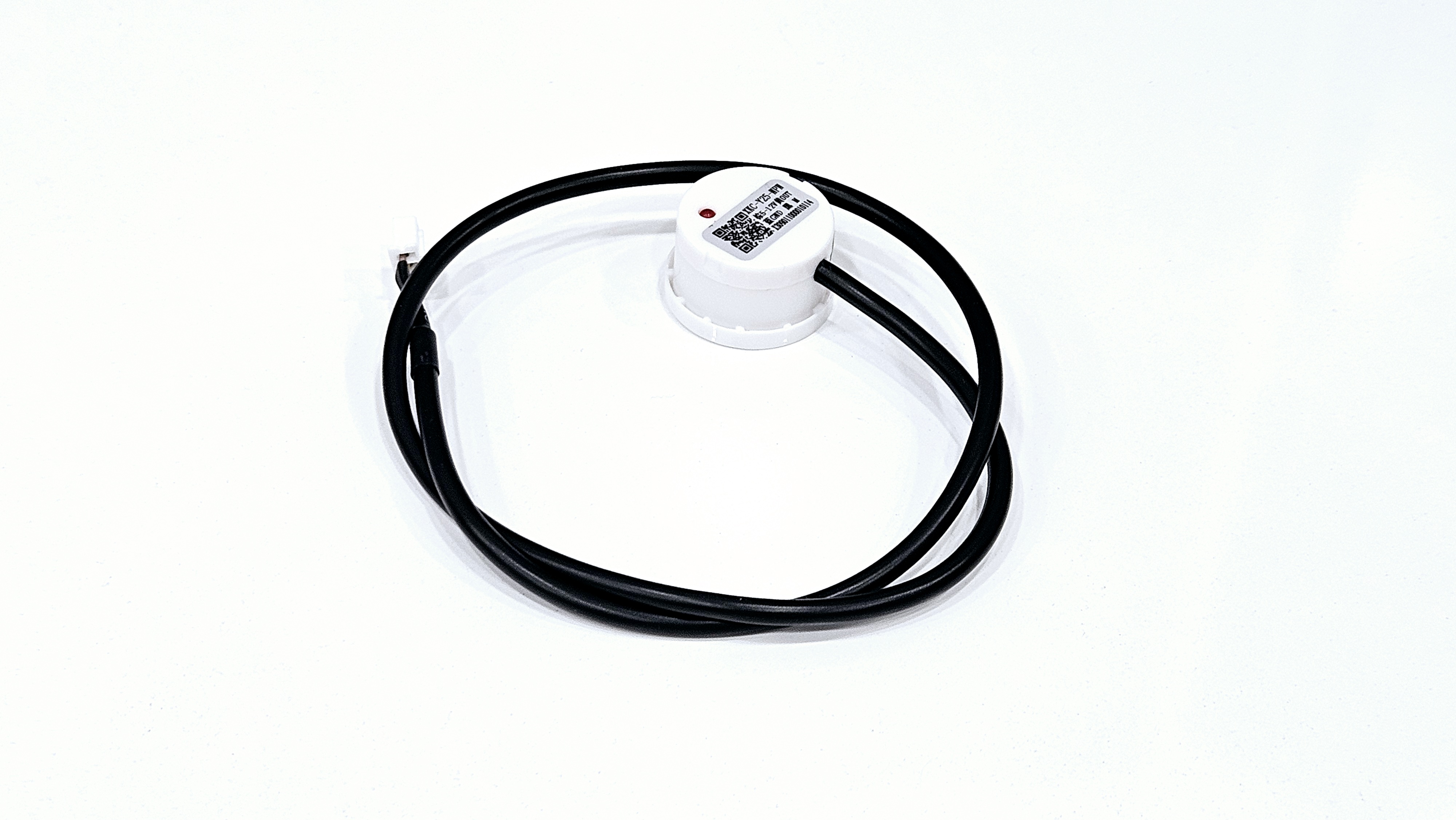
A non-contact level sensor is a device that can be attached to the outside of a tank or container to measure the inside level of liquids
Since it does not contact directly with water, it can be used reliably for a long time and is available to various containers (excluding metal) and liquids.
Specifications
| Characteristics | XKC-Y25-V | XKC-Y25-PNP | XKC-Y25-NPN | XKC-Y28-RS485 |
|---|---|---|---|---|
| Power Voltage | DC 5-24V | DC 5-12V, DC 24V | DC 5-12V, DC 24V | 24V (12V Customizable) |
| Output Mode | High and low level | Switch quantity (high pulse effective) | Switch quantity (low pulse effective) | Communication output |
| Ripple Voltage Requirements | ≤200 mV | |||
| Current | ≤5mA | |||
| Response Time | 500mS | |||
| Operating Temperature | -20~105℃ | |||
| Humidity | 5%~100% | |||
| Measurement Thickness (Sensitivity Range) | ≤20mm (Container Wall Thickness) | |||
| Water Level Tolerance Range | ±1.5mm | |||
| Wire length | 500MM (±10MM) | |||
| Terminal Order | Brown (VCC), Yellow (Signal Output), Blue (GND), Black (COM) | |||
| Material | PC V0 Flame Retardant Material | |||
| Waterproof Performance | IP67 | |||
| Safety Standard Certification | CE | |||
| Environmental Protection Certification | ROHS-2.0 | |||
There are differences in voltage and output modes depending on the model, and this document is based on the XKC-Y25-NPN model.
Usage Example
1. Simple Measurement Test
This is an example of verifying whether the non-contact level sensor accurately measures when placed outside the container.
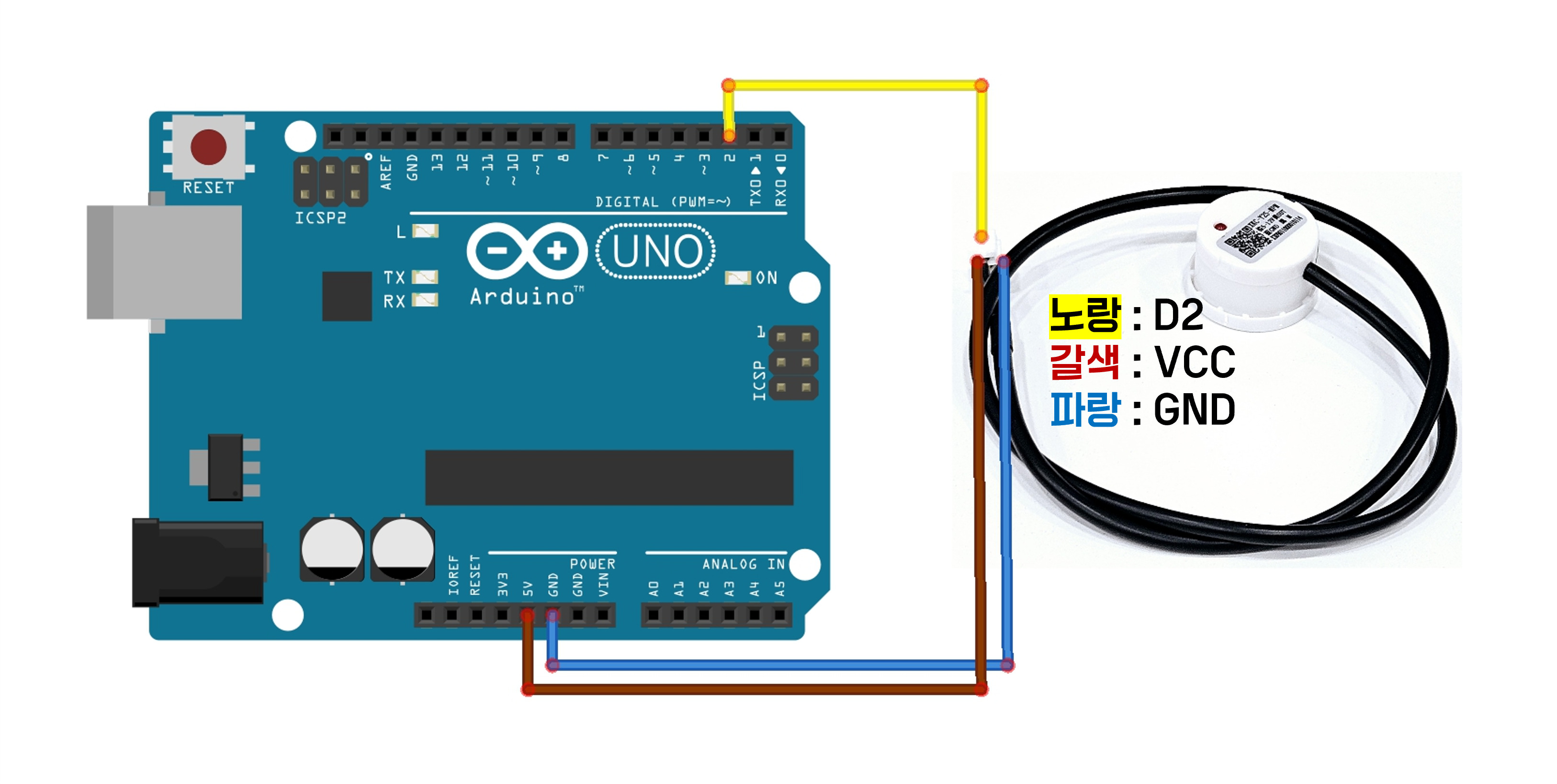
Circuit Configuration
You can check the sensor wire by gently pulling on the shrink tube.
| Sensor Wire Color | Function | Arduino Pin |
|---|---|---|
| Brown | VCC | 5V |
| Blue | GND | GND |
| Yellow | OUT | D2 |
| Black | SET () | Not Connected (or for Configuration) |

Code
As shown in the specifications tab, the output mode varies depending on the model, so it is necessary to check whether HIGH or LOW is output when detecting the water level.
In the case of the XKC-Y25-NPN model used in this document, LOW is output when the water level is detected.
const int sensorPin = 2; // Sensor Output Pin
int sensorValue = 0;

void setup() {
  pinMode(sensorPin, INPUT_PULLUP); // Activate INPUT_PULLUP Resistor
  Serial.begin(9600);
}

void loop() {
  sensorValue = digitalRead(sensorPin);
  if (sensorValue == LOW) { // Depending on the model, LOW or HIGH may be output differently when detecting the water level, so verification is necessary.
    Serial.println("Water Level Detected");
  } else {
    Serial.println("Water Level Not Detected");
  }
  delay(1000); // Measure at 1-second Interval
}
Execution Result
You can observe that the LED built into the XKC-Y25 sensor lights up when the water level is detected.

2. Using Non-Contact Water Level Sensor with LED
This example demonstrates that the LED lights up when the water level is detected and turns off when it is not detected.
Similar methods can be used to combine various modules and sensors, such as buzzers and water pumps.
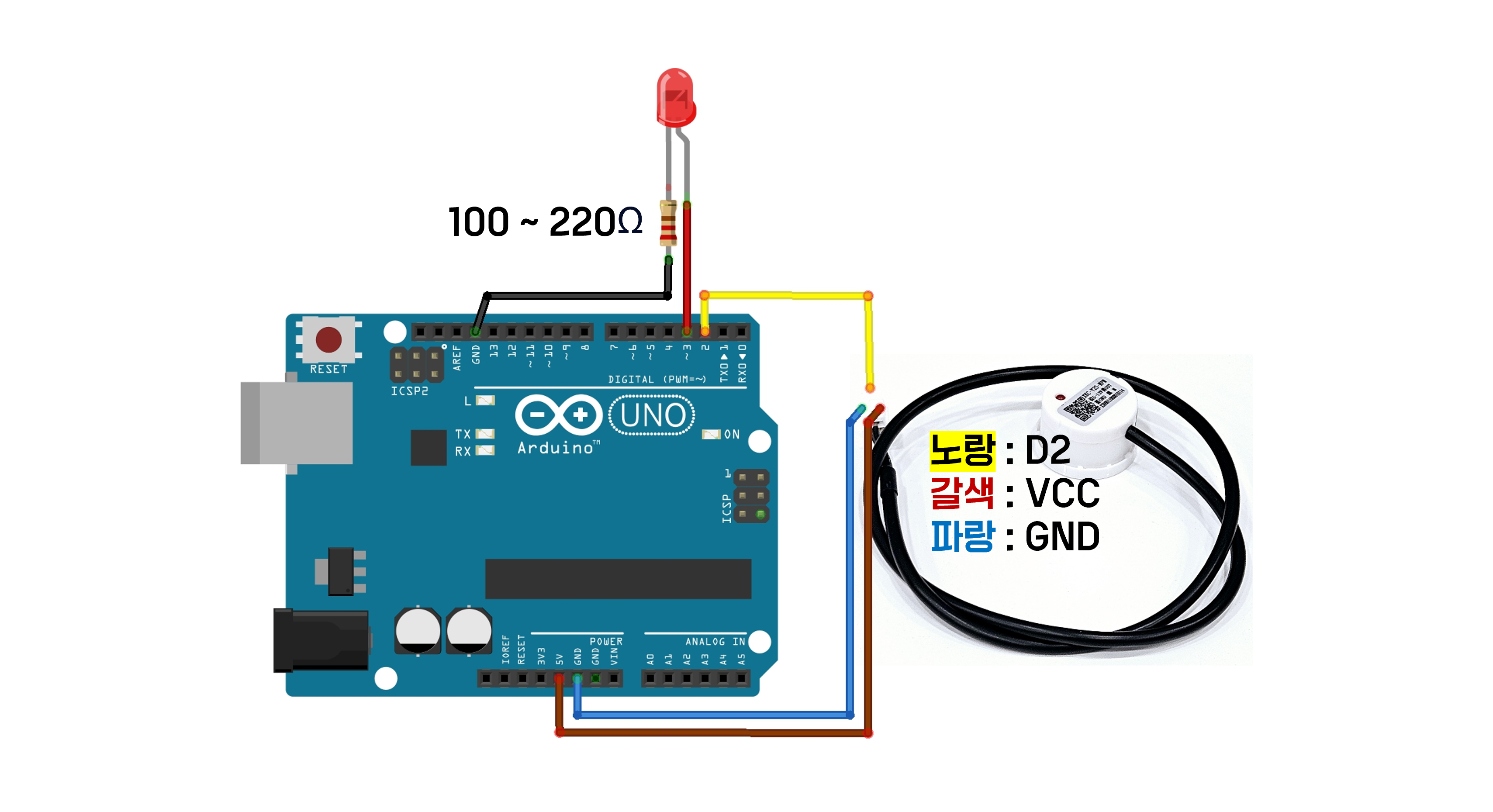
Circuit Configuration
You can check the sensor wire by gently pulling the shrink tube.
Please connect the non-contact water level sensor in the same way as in Example 1, and then add the LED.
| Arduino Pin | Connect |
|---|---|
| D3 | Long leg of LED |
| GND | One Leg of the Resistor |
| Other Leg of the Resistor | Short leg of LED |

Code
As in Example 1, it is necessary to check whether HIGH or LOW is output when detecting the water level, as the output mode varies depending on the model.
In the case of the XKC-Y25-NPN model used in this document, LOW is output when the water level is detected.
const int sensorPin = 2;  // Connecting the OUT Pin of the Non-Contact Water Level Sensor
const int ledPin = 3;    // LED Connection Pin

void setup() {
  pinMode(sensorPin, INPUT_PULLUP); // Set the non-contact water level sensor pin to INPUT_PULLUP mode
  pinMode(ledPin, OUTPUT);          // Set the LED pin to OUTPUT mode
  Serial.begin(9600);               // Start serial communication
}

void loop() {
  int sensorValue = digitalRead(sensorPin); // Reading the Value from the Non-Contact Water Level Sensor

  if (sensorValue == LOW) { // When the water level is detected (when the sensor reads LOW)
    digitalWrite(ledPin, HIGH); // Turning on the LED
    Serial.println("Water Level Detected");
  } else { // When the water level is not detected (when the sensor reads HIGH)
    digitalWrite(ledPin, LOW); // Turning off the LED
    Serial.println("Water Level Not Detected");
  }

  delay(500); // Wait for 0.5 seconds
}
Execution Result
The output in the serial monitor is the same as in Example 1. You can confirm that the LED connected to pin 3 turns on when the water level is detected.
Applications
- Home Water Level Monitoring: Water tanks, water purifiers, aquariums, etc.
- Industrial Level Control: Chemical tanks, storage tanks, drainage systems, etc.
- Agriculture: Water level monitoring in irrigation systems.
- Medical: Level detection in medical liquid storage containers.
Cautions
- Container materials can vary and include plastic, paper, glass, etc., but metal containers may cause issues with sensor operation and are not suitable.
- The external surface of the container where the sensor will be attached should be clean and dry during installation.
- The thickness of the container must be within the detection range for accurate measurement.